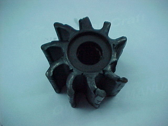
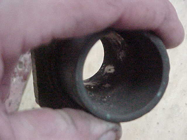
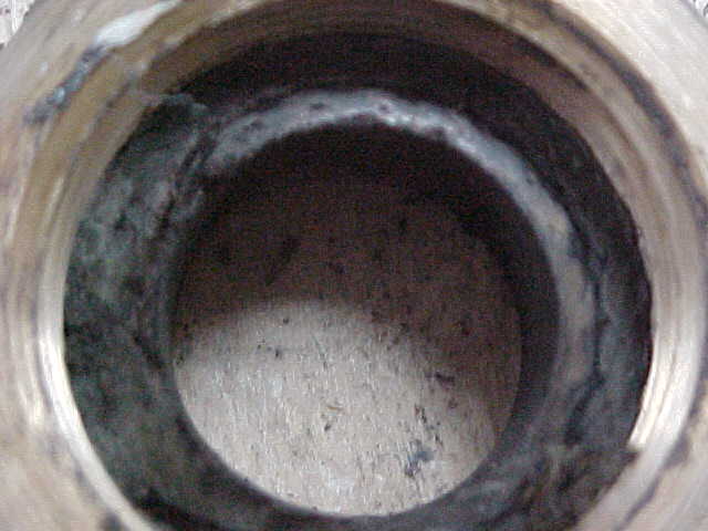
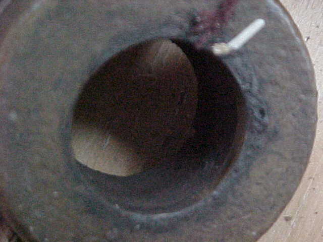
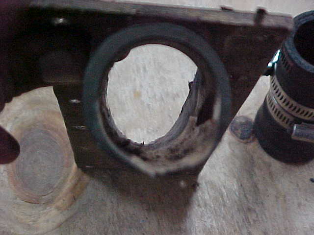
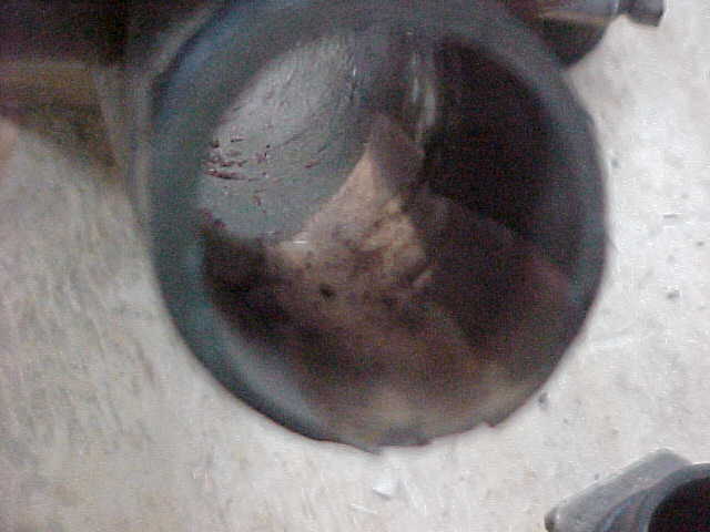
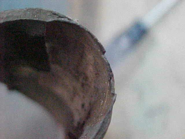
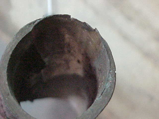
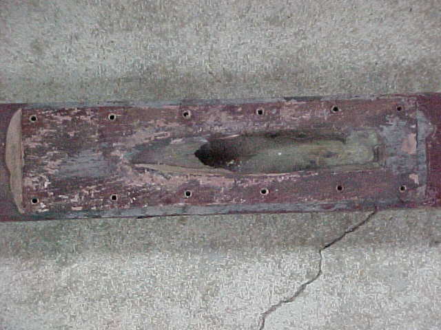
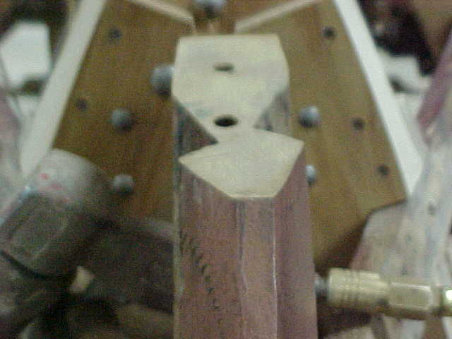
This is your water pump impeller. Note one "fin" or vane is completely missing!
These typically last only 3 seasons.... in fact most boat owners change them every year as cheap insurance against problems. I think every year is a little excessive. On the flip side... I tried to run one of mine a fourth season.... bad idea! The engine overheated at the boat ramp and I had to remove every hose to find all the parts of the impeller that had disintegrated!
We discovered this during the survey and you may remember we showed pictures of it to you then. Before installing the new impeller we will back flush the discharge hoses from the pump to find / remove the missing pieces of this old impeller from the water passageways of the engine. If we do not, these may block critical water passageways in the engine and lead to localized overheating of and damage to the engine.
New Toll Free Phone Number 866-921-BOAT (2628)
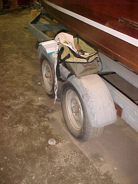
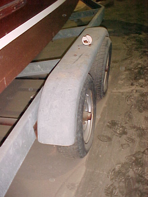
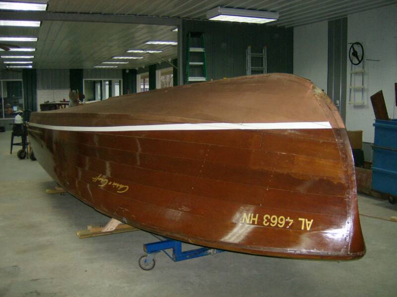
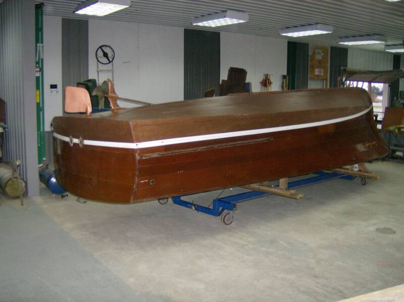
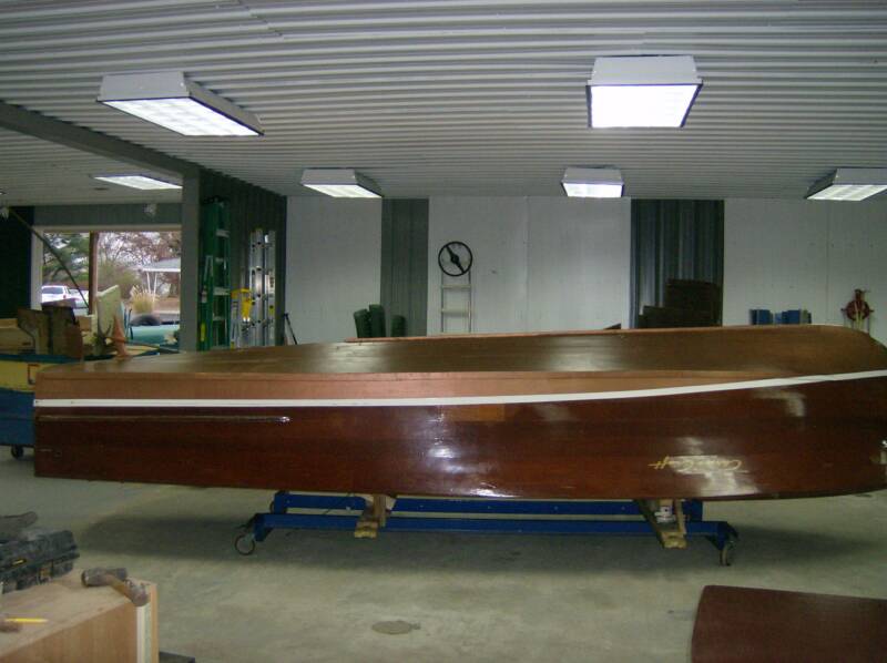
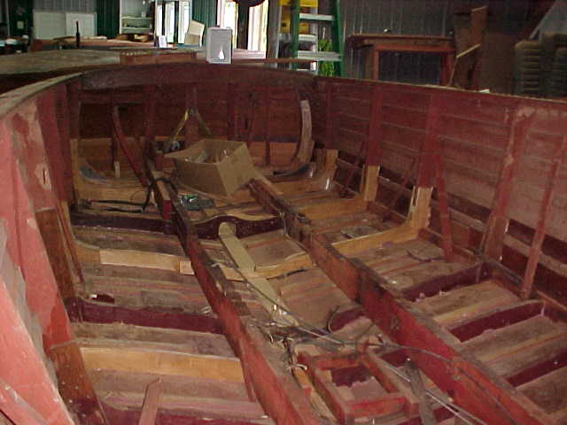
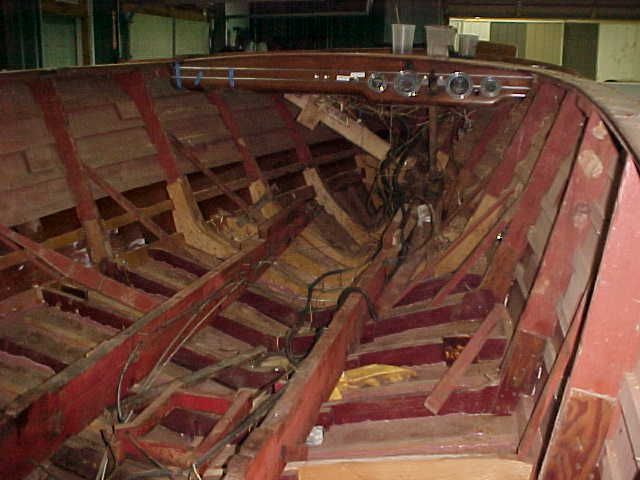
The Process started with a survey of the boat in Guntersville, Alabama. This page documents the condition of the boat and trailer before we started the restoration process.
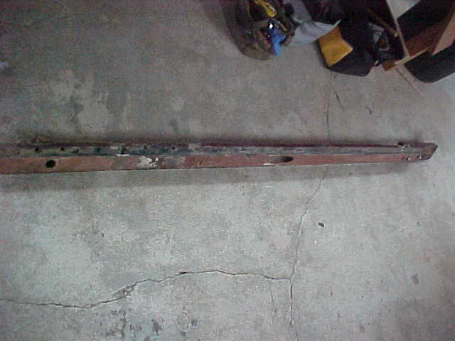
The trailer had at least one wheel bearing problem - note right hand photo front wheel / axle. As it turned out on boat pick up day, 3 of the 4 bearings were out. There were not even any rolling elements (tapered rollers) in the front right (starboard) bearing and the spindle had been badly damaged. There was some concern the trailer might not make it to our shop due to the condition of the spindle but it did! The bearings were changed in 98 degree heat and 90% humidity in an uninsulated warehouse!
Update 11/09
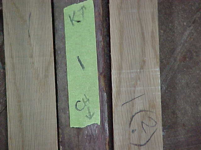
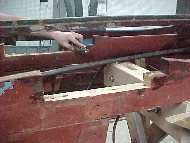
Port side bottom coming loose. This requires core drilling all screws and lifting both layers of bottom carefully in one piece,
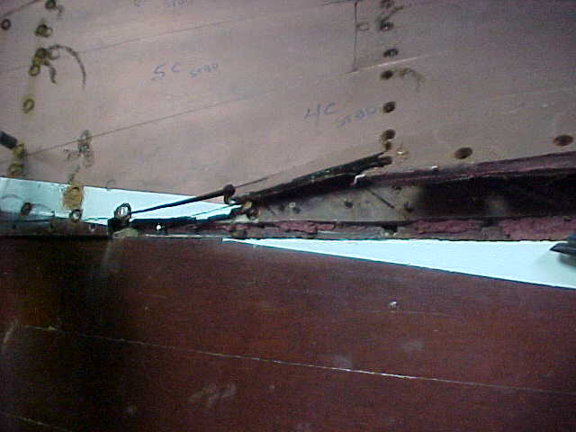
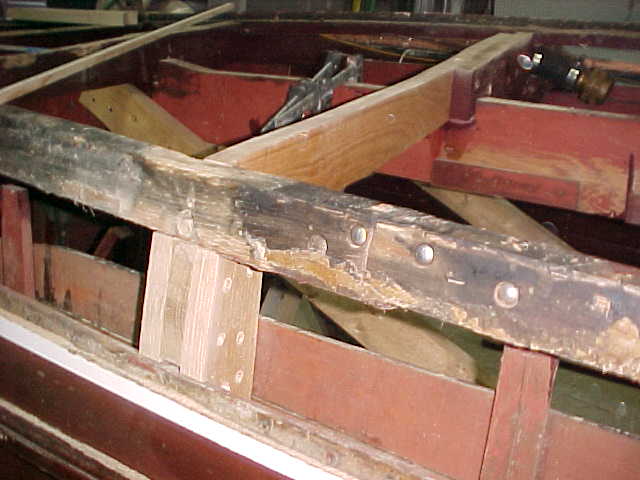
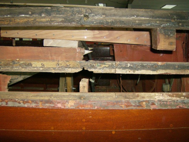
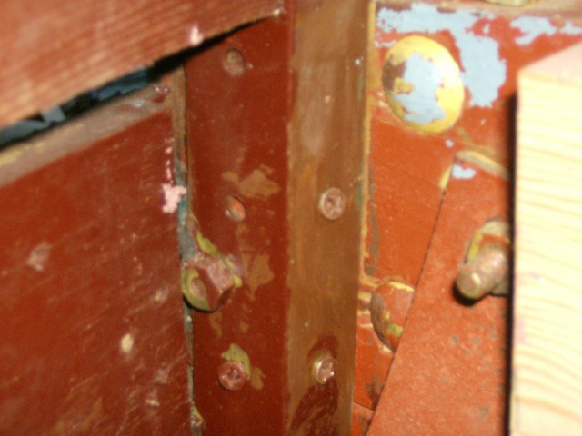
port forward chine/bottom, showing extensive adhesive holding sealing seams and extra screws holding bow area together
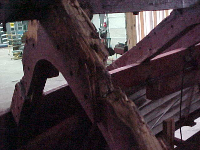
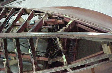
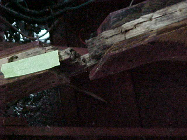
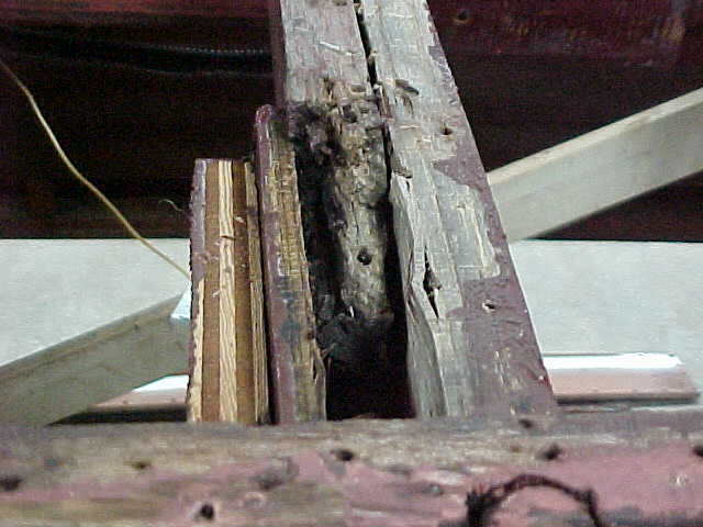
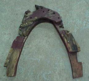
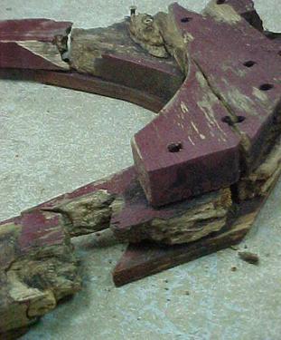
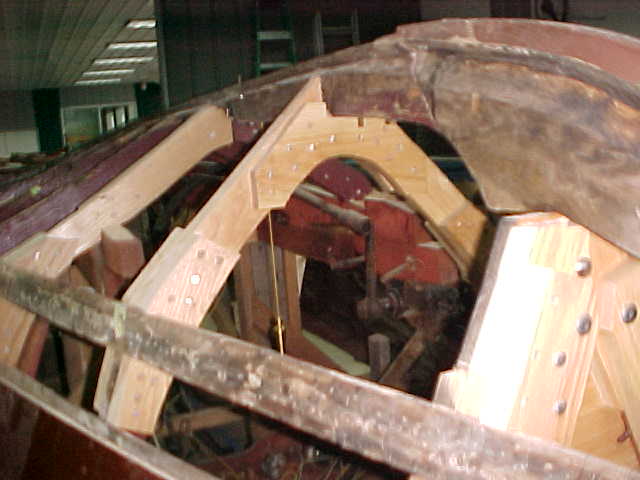
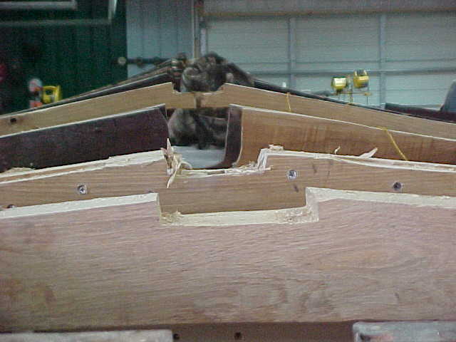
Above pic shows extensive rot of one of the bow frames
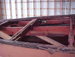
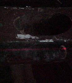
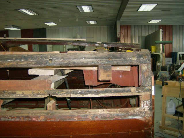
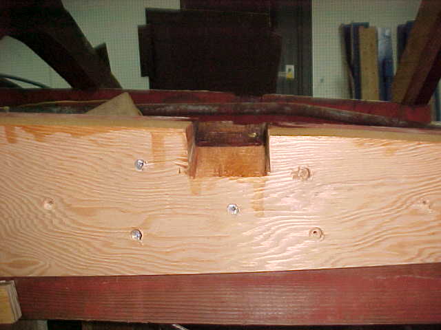
Above shows shaft log area after cleaning and bottom removal
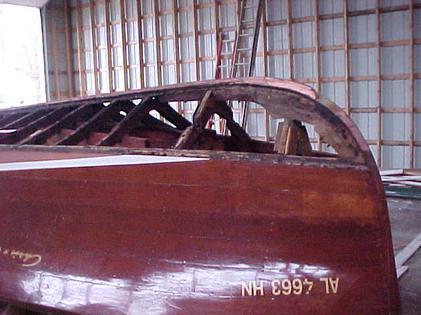
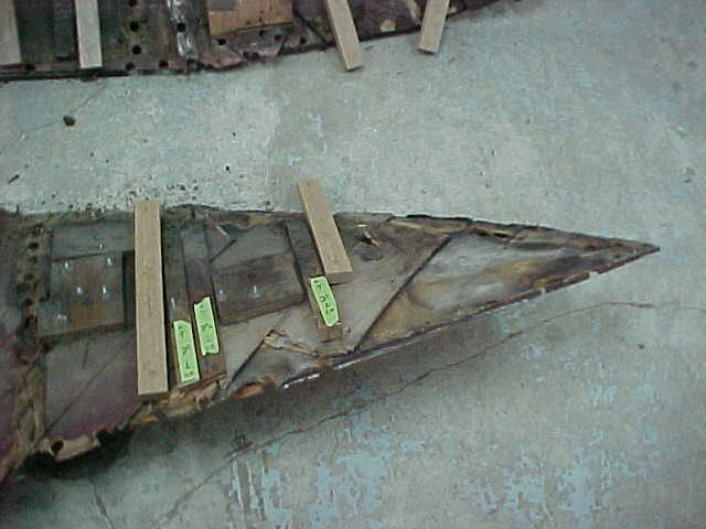
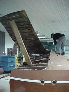
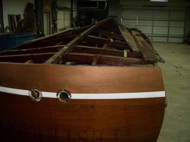
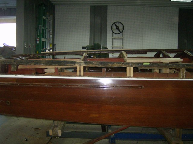
pic of the bow of Yesterday with bottom removed
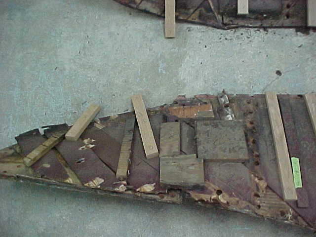
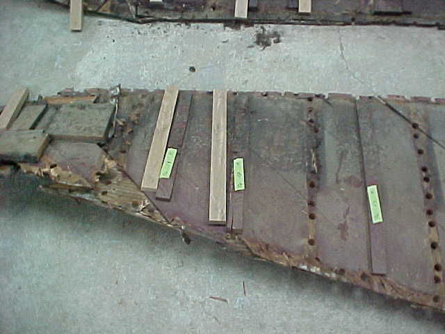
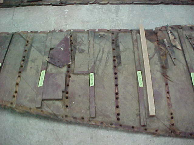
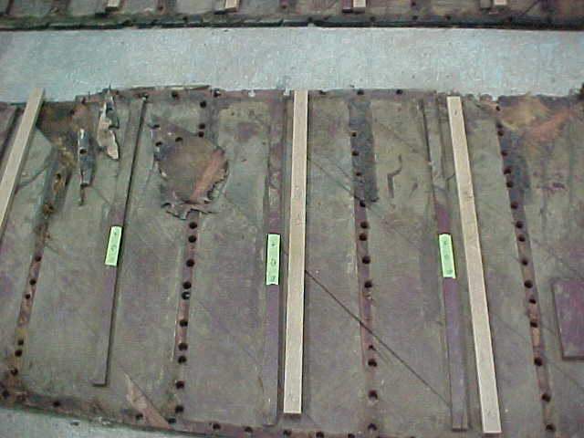
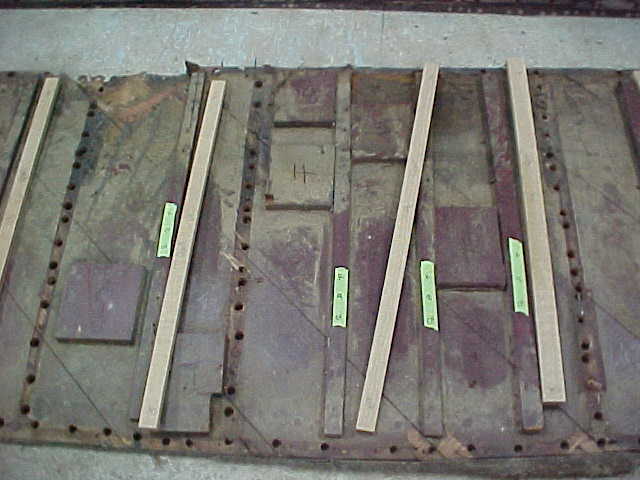
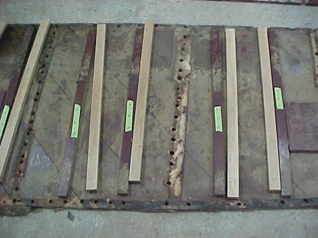
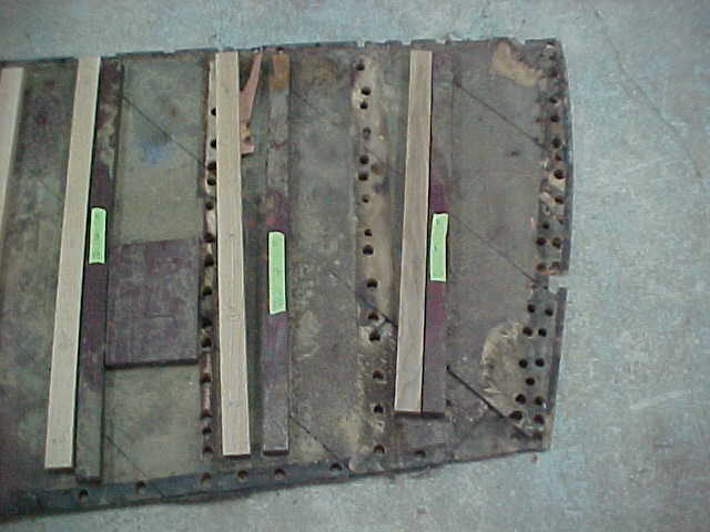
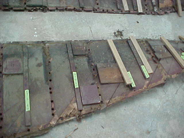
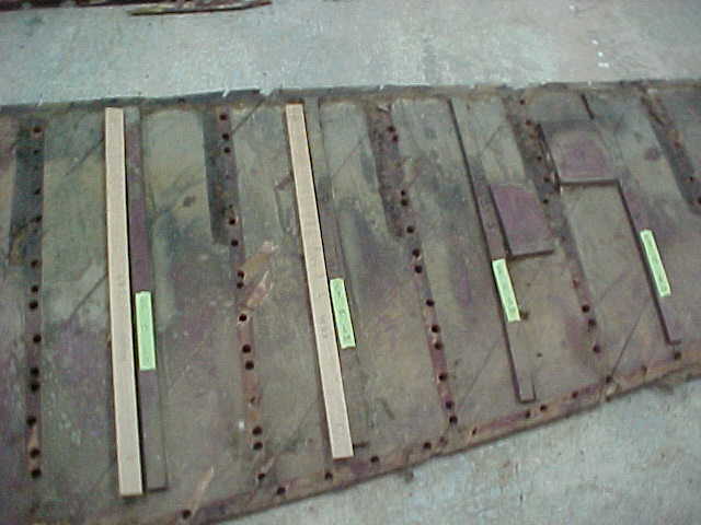
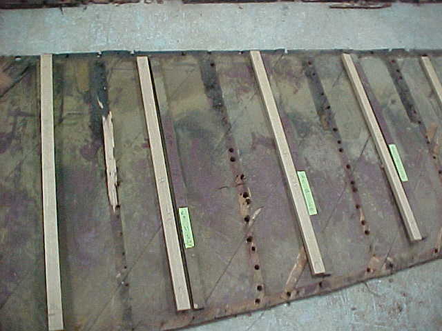
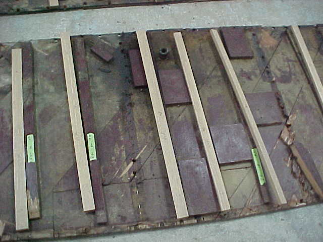
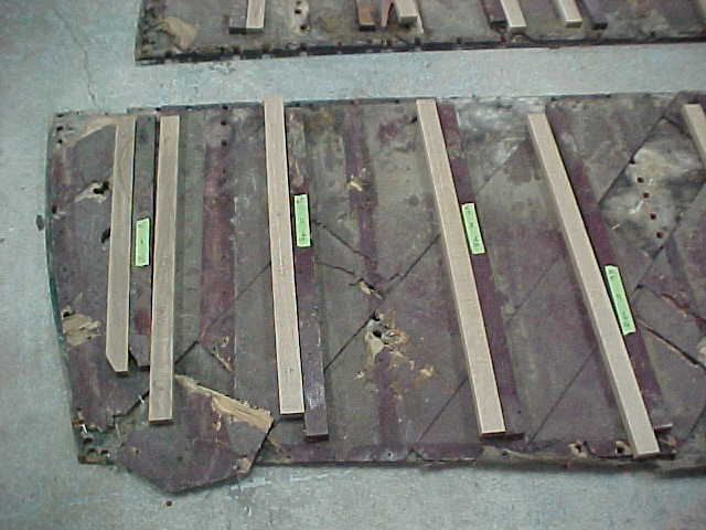
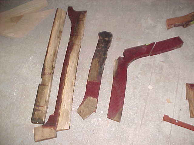
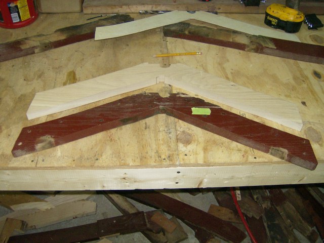
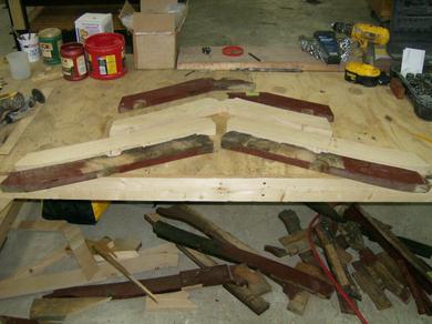
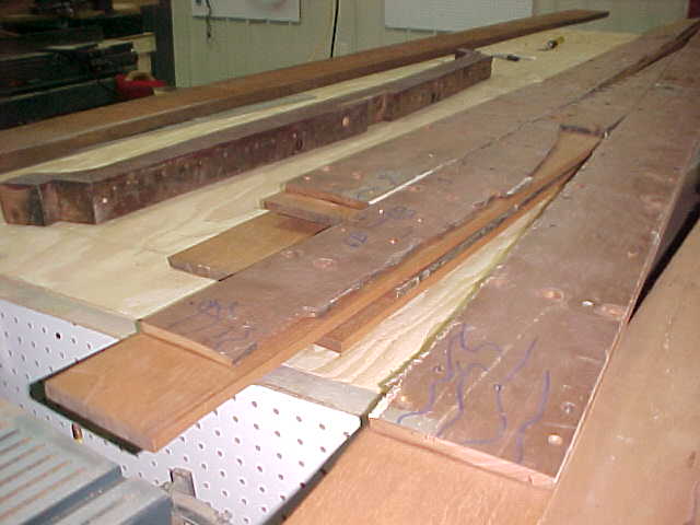
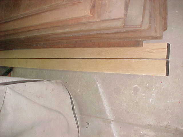
Below 14 pictures are of the bottom two sides after removal being identified and cataloged so we can duplicate new pieces with precision, also shows new battens made and layed out next to old ones.
1
2
3
4
5
6
7
8
9
10
11
12
3
2
4
5
6
7
8
9
10
11
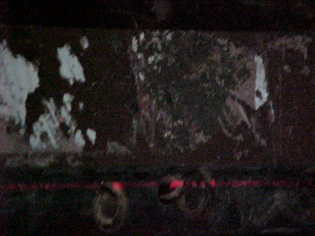
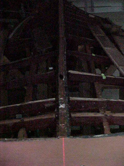
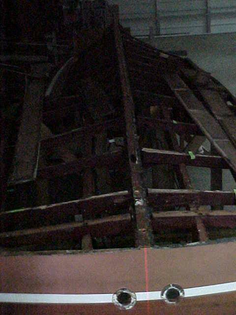
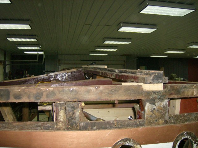
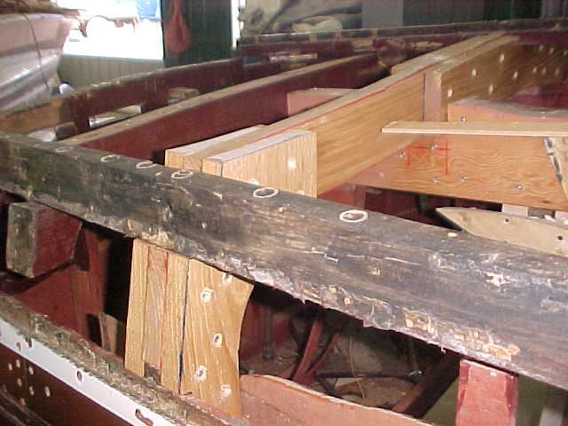
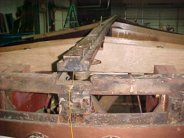
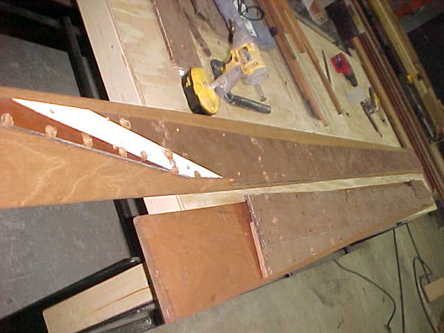
Below is pics of keel with laser line showing slight bowing of keel of about 1/4 inch at the shaft strut framing area.
Below are 2 pics showing laser line along stbd side of keel and displaying approx 1/4 side bend, the 2 arrows show the edge of the keel and the laser line and as we can see there is a small sway of about 1/4 inch
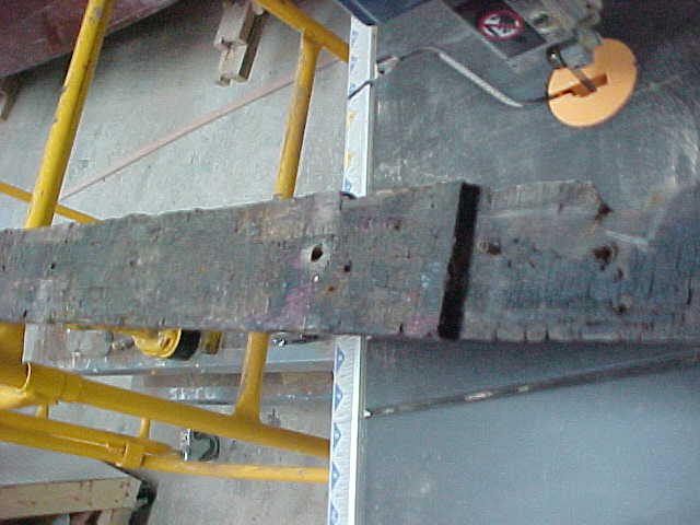
above is fr 1 port side showing decay, beam is completely rotted thru.
below is fr 1 stbd side showing decay, and again it is all the way thru.
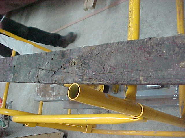
below is fr 2 port showing decay, the wood is flaky and gouged
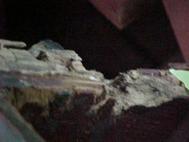
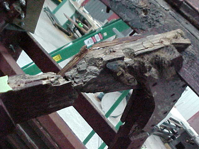
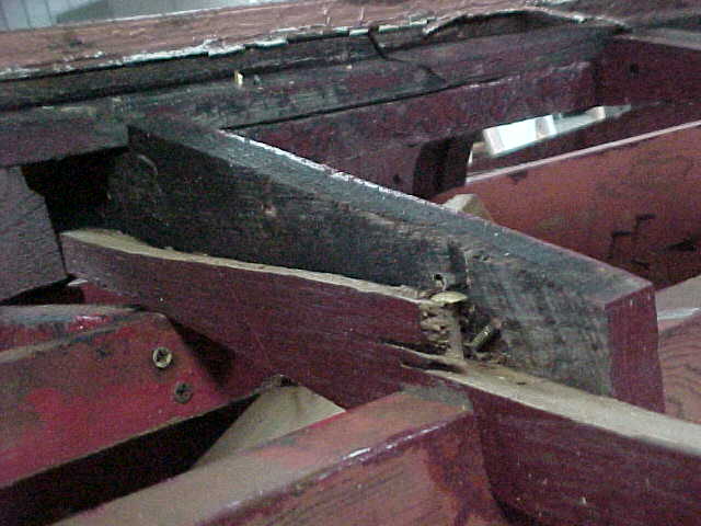
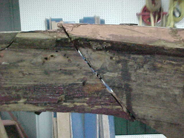
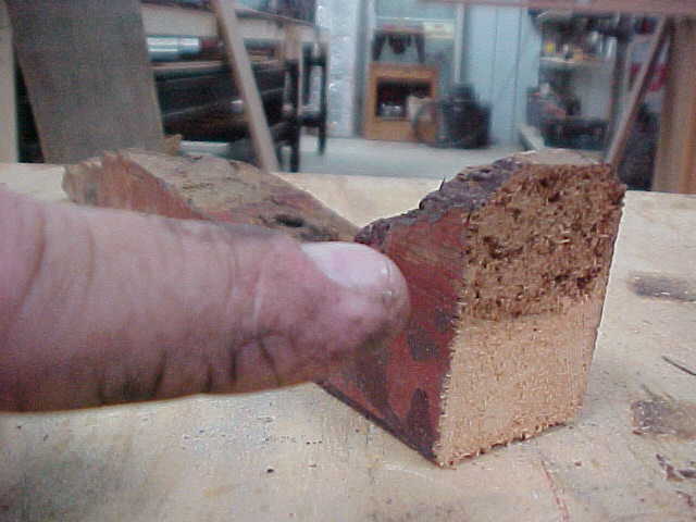
below is fr 3 port showing decay, end grain demonstrates how decay spreads. Notice dark area and seperation between beam and sister boards.
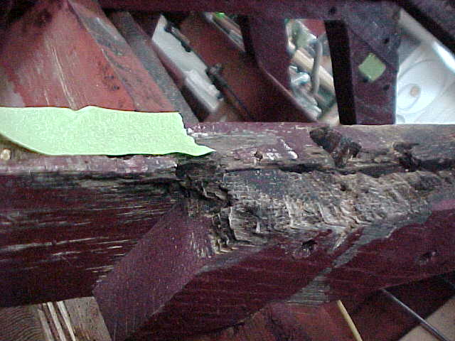
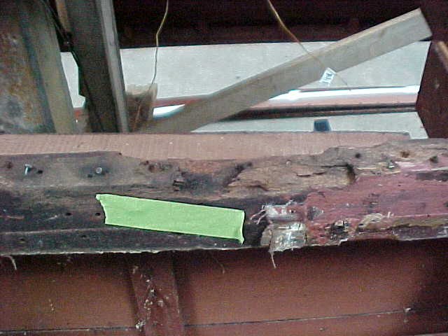
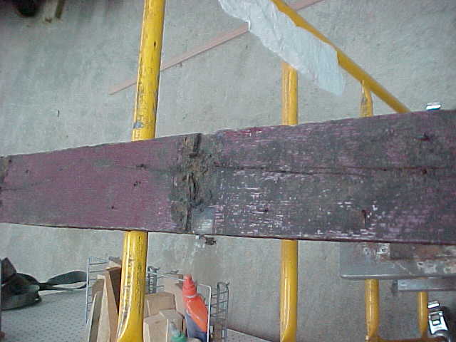
stbd side fr 3 showing crack under chine area, this will be replaced along with the rotted beam.
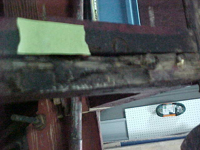
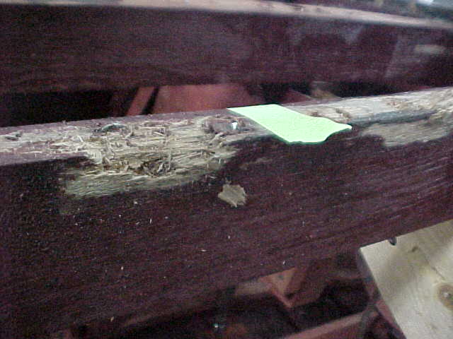
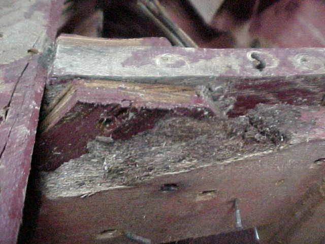
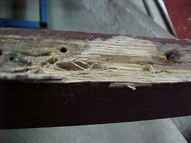
fr 4 port showing decay on frame and sister, this has encroached down about 1/4 inch deep
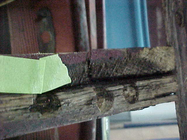
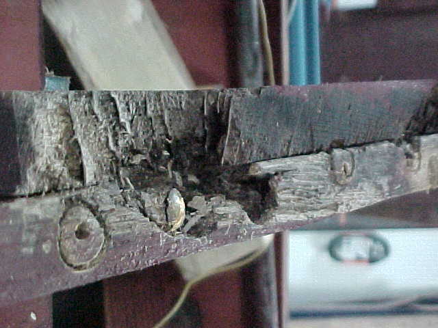
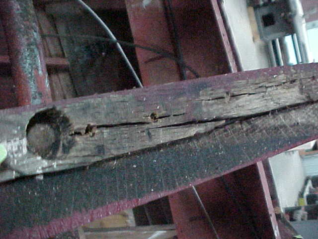
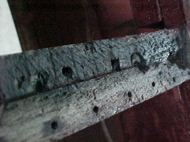
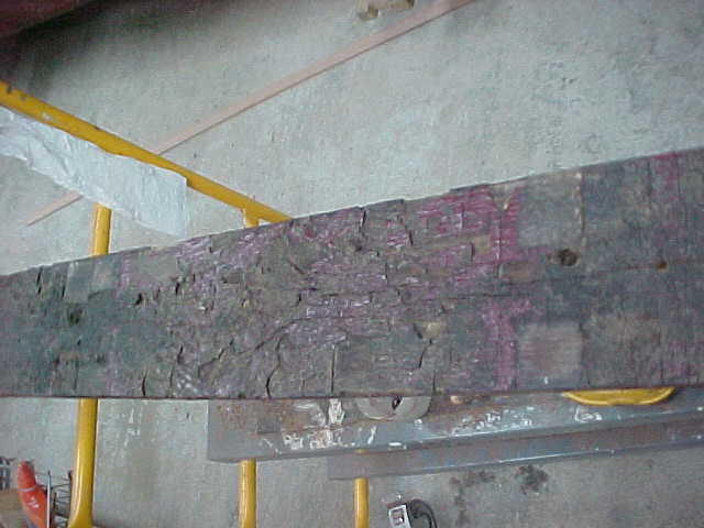
fr 11 port side showing decay and at keel you can see the rot exposing the through bolt connecting to the keel
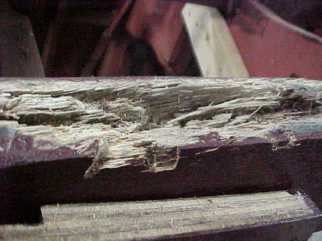
fr 12 port showing lot of decay. This frame was flaking and peeled with the touch of a finger.
fr 13 port showing flaking wood decay
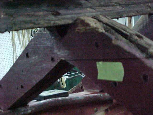
fr 1 stbd looking fwd, major decay. Not much holding this together, so it will be reborn with new.
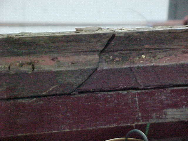
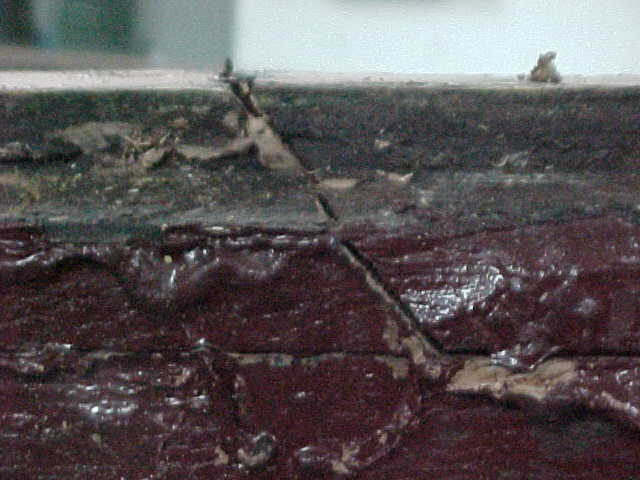
fr 3 stbd showing cracking, which is weakening the rib.
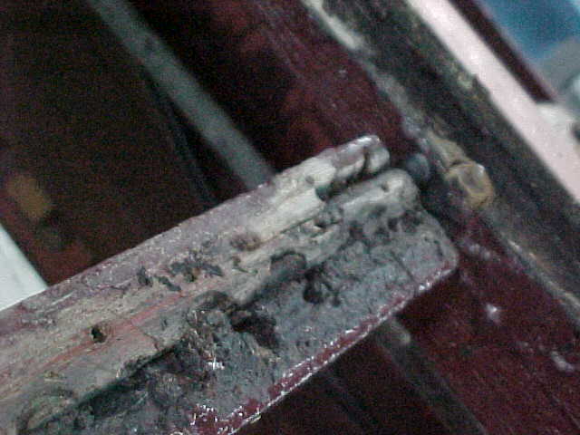
fr 4 stbd side where it attaches to chine, this shows block falling appart and rot is powder form.
fr 4 under stbd stringer. Arrow shows stringer running under frame.
fr 9 stbd showing split framing, which was already there but when the bottom was removed it came apart.
fr 11 stbd where it attaches to chine and as you can see it doesn't even reach the chine. Arrow shows chine.
fr 11 running under stringer and keel
fr 13 showing flaking, major decay ongoing. This frame was soft to the touch and screws came out by finger
another of fr 13 showing decay
stbd chine at fr 1 showing split
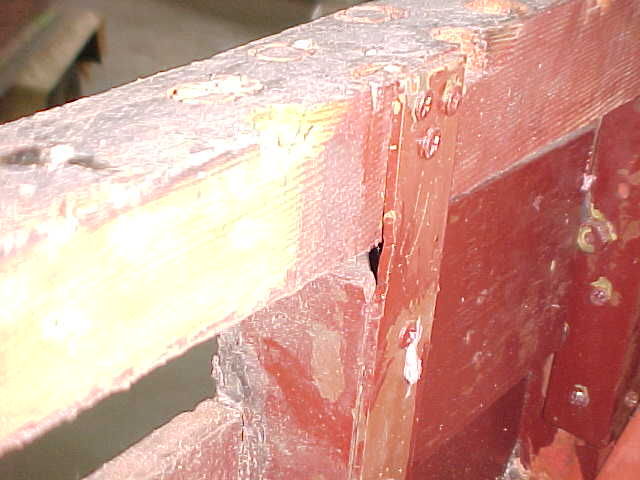
stbd chine at fr 7 showing butt block and bad splice, notice the gap between the two pieces.
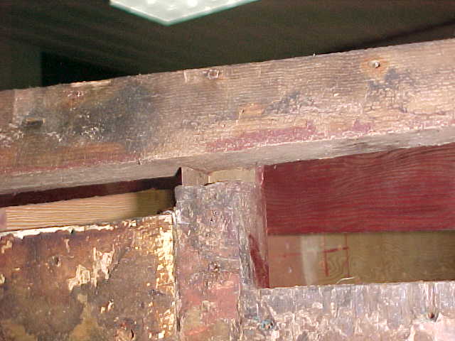
chine at fr 8 & 9 showing damage
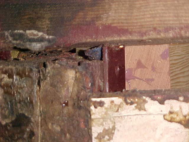
chine stbd side showing damage at fr 11 area
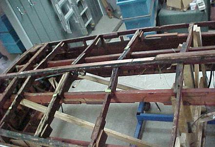
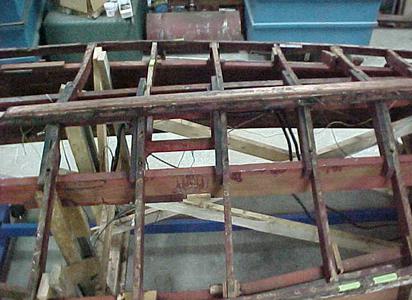
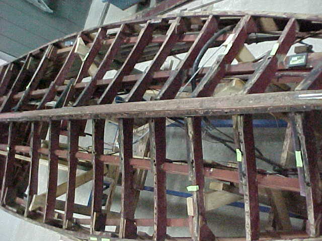
Picture to the left is of the open bottom with ribs numbered for reference to the below pictures. They are numbered from bow to stern.
Below pictures are of the bottom removed and frames numbered as above for referencing below pictures showing decay or damage.
The chine on the stbd side has been repaired several times and was not done in the correct method. We will remove and replace this with proper matching material and newer methods, therefore eliminating the week areas and worry of rot in your lifetime.
Old battens have tape on them for identification and new ones cut and laid out along them for reference.
keels first splice from stern
about 14 in fwd of first splice is front splice of same piece in keel
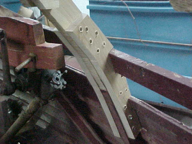
keel splice at knee
another look at knee splice with another splice just aft at frame 1
under knee several attemps of supports, this is frame 1a
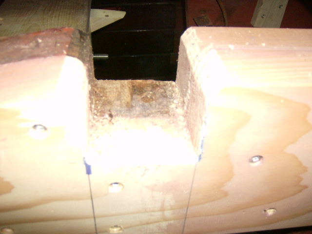
another look at approx 14 in splice under engine mounts
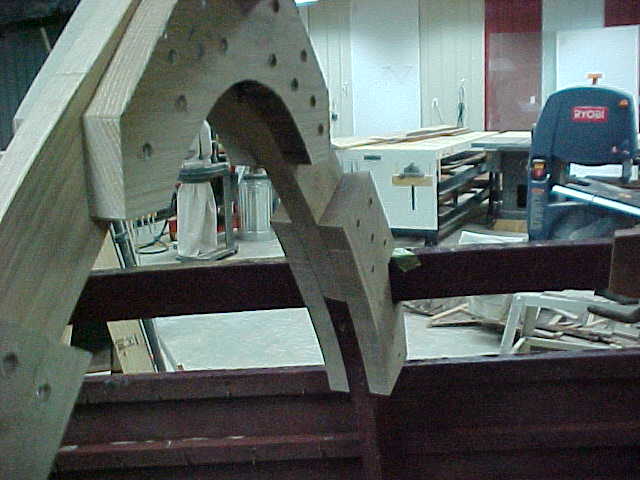
a picture says it all, WOW!! what a curve
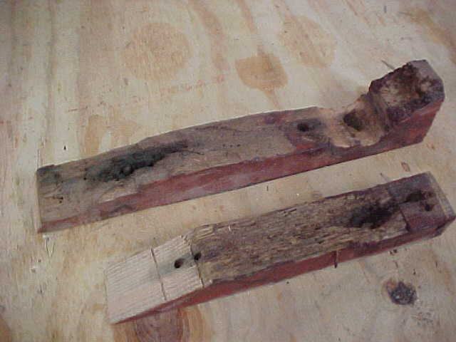
frame 1 removed carefully for restoration
closer look at frame 1 showing excesive decay
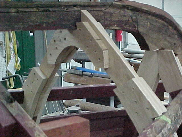
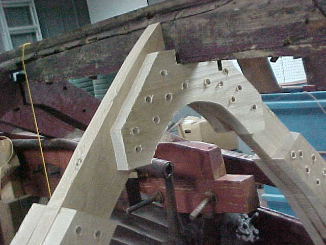
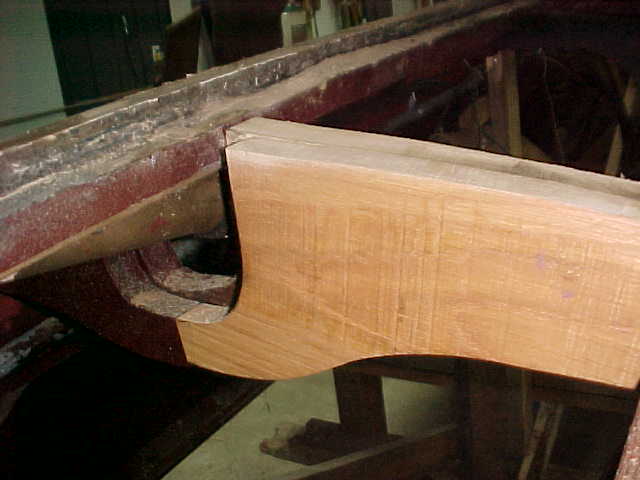
The below 4 pictures show the new frame 1 being installed and above right shows the old piece for comparison. What a difference! Things are coming along at a good pace.
# 1
# 2
# 3
# 4
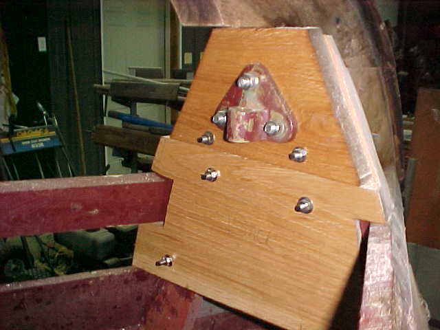
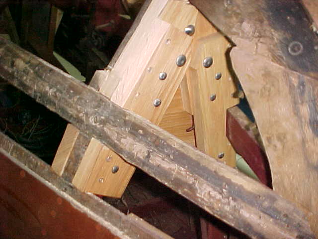
Below is 2 pics of frame 1a being reinstalled which is under the Knee of the keel for support and to add strength for the lifting rod. Old framing did not connect the lifting rod to the keel so boat was being lifted by frames alone.
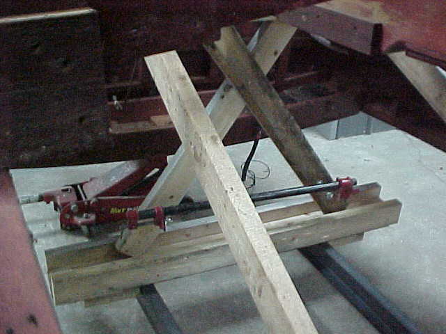
Below picture is of a support/lifting jack to allow adjustment of the stern height for the keel sway shown in before pictures. This was thought up and put into practice for your boat to ensure we put everything in it's proper alignment.
1 a.
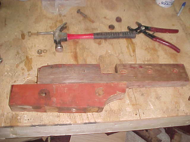
Below 2 pics are frame 10 old pieces showing the joint area at the chine and how it has 3 splices within 10 inches. Not a good thing! Arrows show the splice joints.
Closeup of frame 10 splice joint at the chine. This was probably done due to rot found and was an easy repair at the time, but not a great way to do it as it leaves a weak joint at a high stress area.
Here are a few of the pieces removed from frames 11 and 10 stbd side
A view of the frames 1a, 1, 2 looking aft after they were faired in by Paul, which means he ensured they have the same contour as the originals which were removed, therefore we will have a tight fit with the bottom planks.
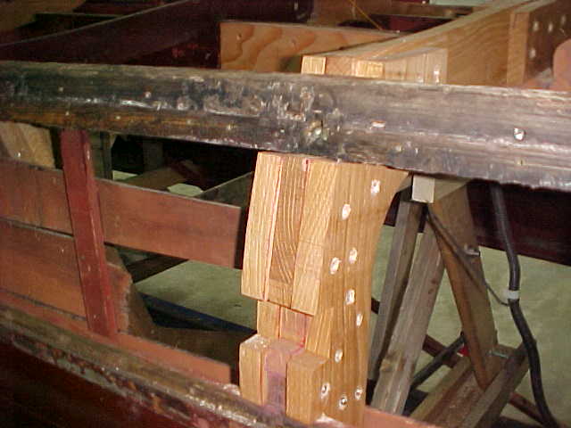
View of frame 11 after replacement. One continuous piece frame keel to the chine to give max support and strength.
Frame 10 new piece being fitted, showing the shaft log cutout
As a note to keep you up to date, we had a discussion with Chris Smith, grandson of the founder of Chris Craft about the frame fairing and wether or not they have a concave or convex fairing. Per conversation it was noted that on cruisers there were two teams, one for each side, and they never agreed on this issue as it did not make any difference on the performance of the boat due to the minor difference it made. This mostly concerns the bow frames as the bow is only in the water at very slow speeds and is out at higher speed. ( A saying they used at the factory was, "The fish don't care!" ). The frames from amidships to the transom are maintained closer as the boat runs on this area at speed and we want to have a flatter, smoother surface for handling and speed performance.
arrows show splice joints
arrows show splice joints
Phone call with Chris Smith, grandson of the founder of CHRIS CRAFT---Dec . 3,2009
below is fr 1a new really beefed up for lifting , notice the notched area giving extra support for lifting, this is on both sides.
fr 1a from bow showing support and thru bolting, also notice these are also notched for extra support.
Below 2 pics show frames being copied, old to new
Bottom of this pic shows old pieces of frames reworked
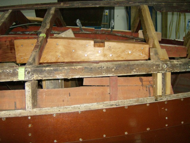
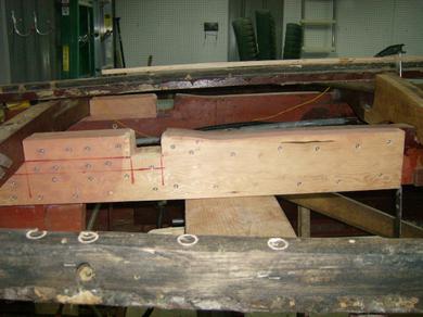
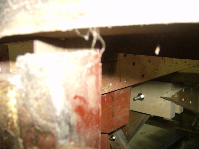
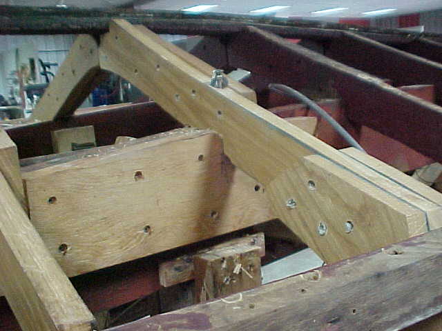
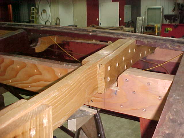
Below 2 pics show forward stringer at steering box area being reworked/sistered with douglas fir so new ribs can be install and reattached with thru bolts.
Aft port stringer sistered with douglas fir after rot was cut out. We also applied 5200 between boards then screwed into place. This gives a better than wood adherewnce and also prevents water from getting into the gaps
Aft stbd stringer sistered same as port. This is also allowing us to reset the proper angle of the keel and demensions of the bow beam .
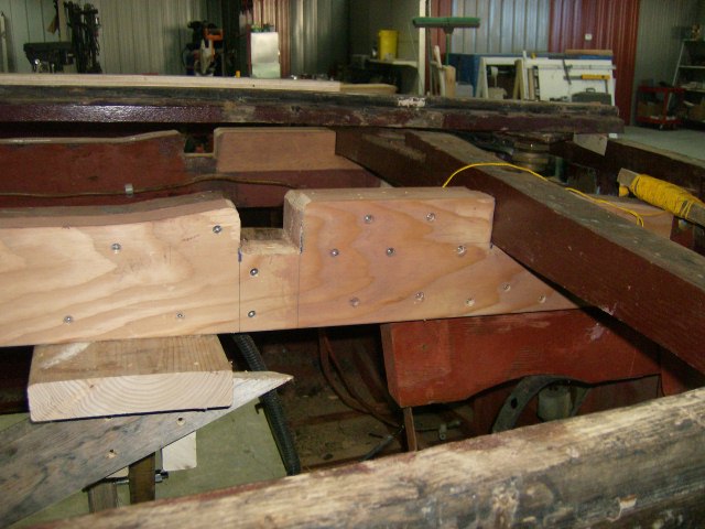
Close view of notch in new stringer to allow rib to set into place for strength and securing.
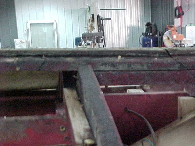
Not so good pic of beams on the stern that were cut off sometime prior due to rot and connected with angle strips but not fully attached to old beams and allowing bow beam to be lower than required.
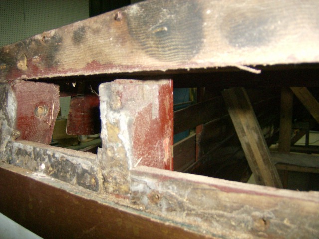
Bow beams not resting on support frames from old repair to transom
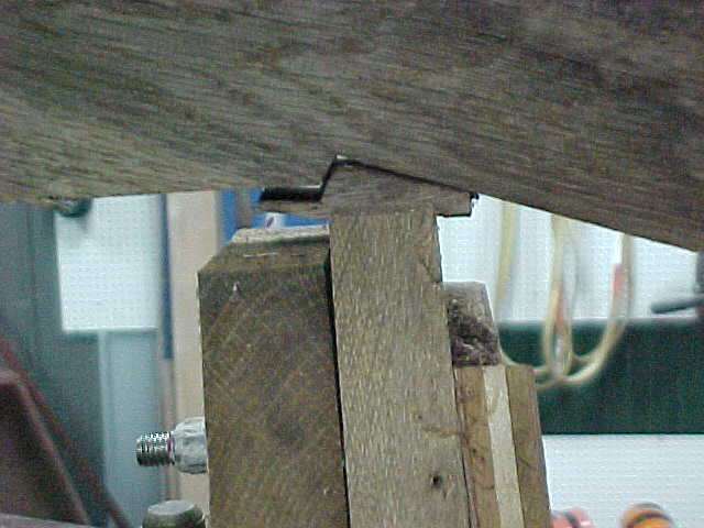
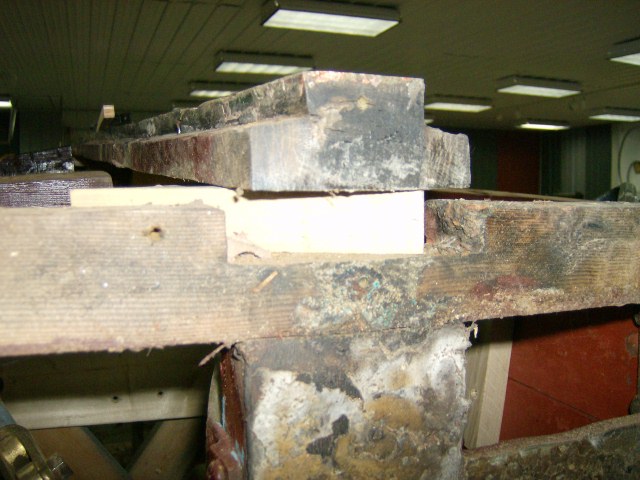
Pic showing keel raised to the proper height with spacer block holding it up. It was sitting down in the notched beam which was not the correct demension allowing improper angle of the keel.
Stbd aft chine and framing, showing bad frame and battens to be replaced
Another pic of stbd aft chine area
Pic showing keel in proper alignment. Note the block in the notched bow beam holding it up approx 1.5 inches
Side view showing keel laying with proper angle frtom bow to stern
View of one of the angle brackets used to hold the bow beam in place from a previous repair
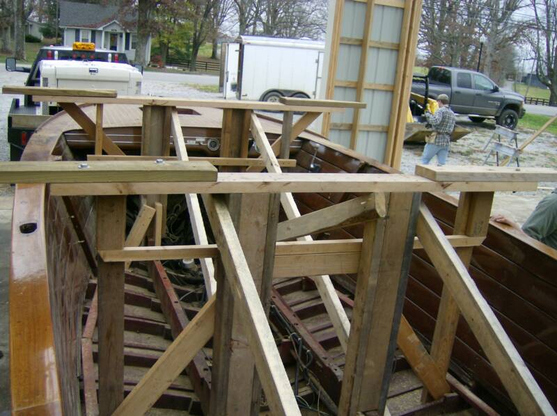
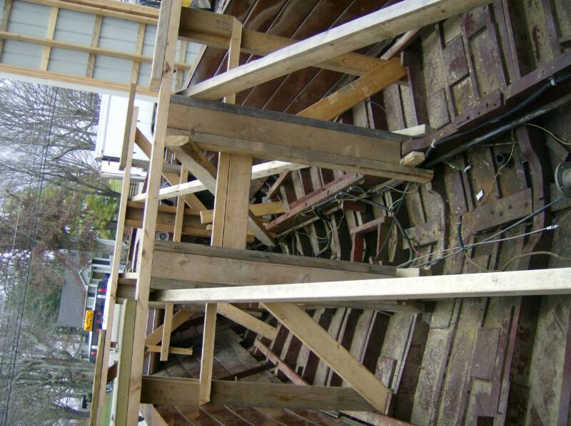
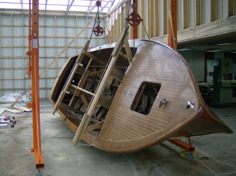
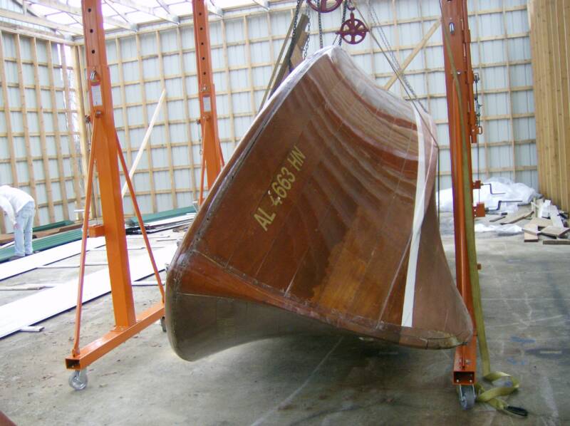
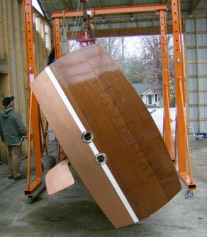
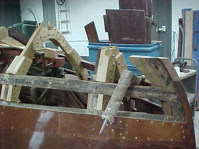
Below are several pictures of the boat in process of being flipped over on a frame carriage, it will then rest on a mobile base to allow moving around for repairs within the shop at different locations as needed.
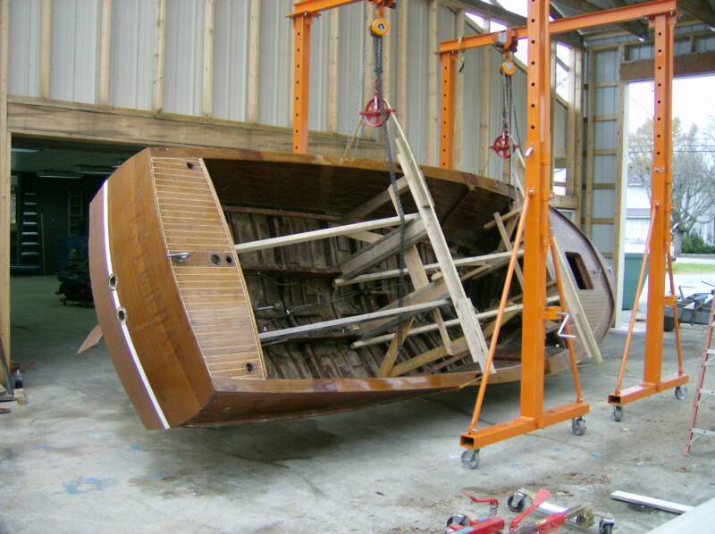
Below pics show boat resting on the mobile base in the shop at the rough work area
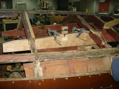
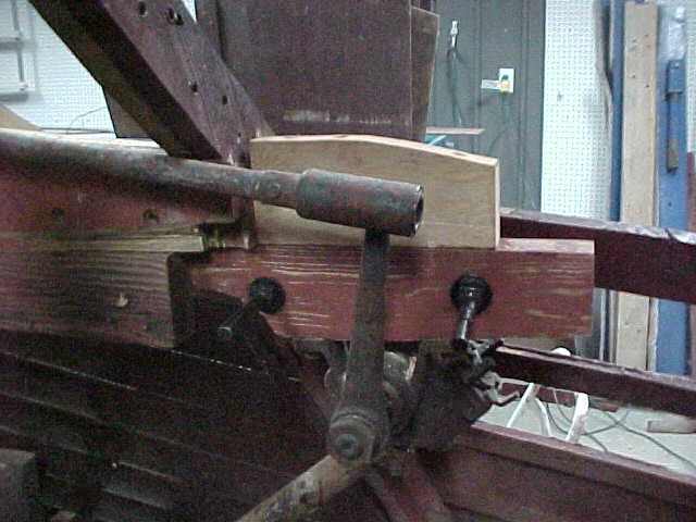
Picture of the steering box framework removed to allow repairs
Pic showing the steering box frame reinstalled with repairs made and reconnected
Below are 2 pieces cut out of the aft stringers due to rot
A closeup of a piece removed from aft stringer showing rot and good wood. We cut below the rot enough to ensure it does not return, and we CEPES all cut and new wood to seal from moisture and prevent rot
Aft stringers being filed and planed to get a proper fit of the new pieces and to ensure all rot is removed.
New piece of stringer aft sowing notch for frame member and also showing runs from CEPES. All of the wood was coated with cepes to prevent moisture penetration
Frame under the engine area replaced and stringer sistered for added support,frame 4 from stbd side
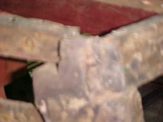
Out of focus pic of the port corner where previous repair notched the beam to fit we guess as they were trying to fix it with as little disruption as they could, which worked but does not make it right.
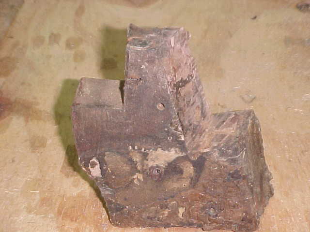
Here is a good picture of that same piece removed to allow a good view of the notching to allow bottom frame fitting
Nice view of the angle pieces used to secure repairs made to the stern in the past.
Again angle bracket holding bow beam in place but holding it approx 1 in above the framework that should have been attached to it securely, see arrow showing angle and gap
Another view of another frame repair with angle to connect after cutting off some rot sometime in the past.
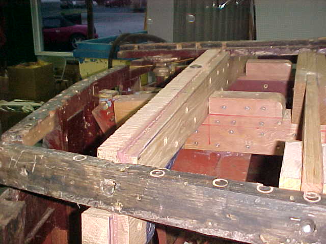
Below shows laser line being used to check verticle and horizontal alignment of the keel and chines.
12/15/09
13
frame 12 stbd side now replaced
frame 12 view at keel from stbd now replaced
frame 12 from port now replaced
frame 13 from port view now replaced
frame 13 viewed from stern showing lifted keel
New bottom planks being copied from existing wood
another view of new planks copied from old wood
two new keel boards milled 12/17/09
arrow shows frame 13
bottom framing with old keel removed
view of framing from front with old keel removed
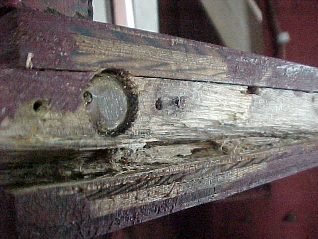
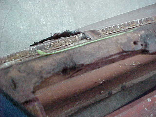
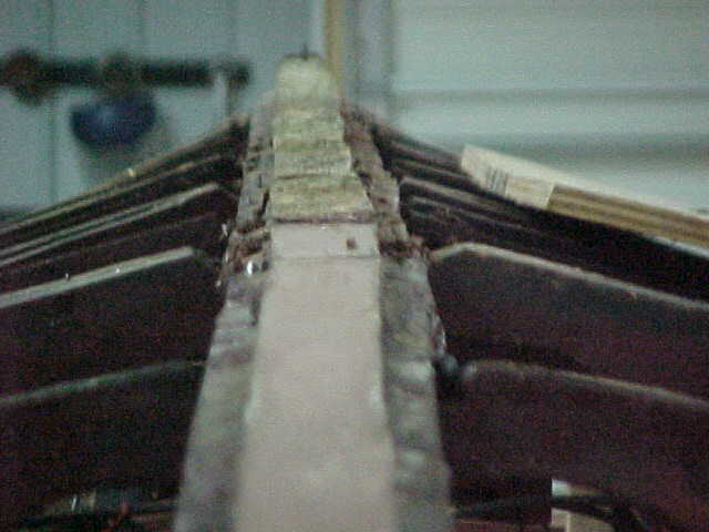
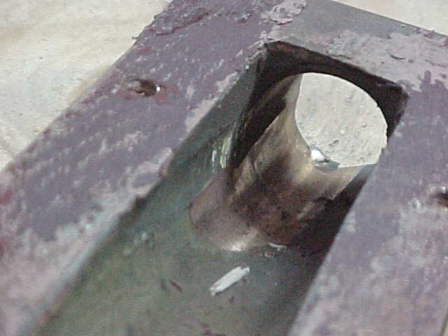
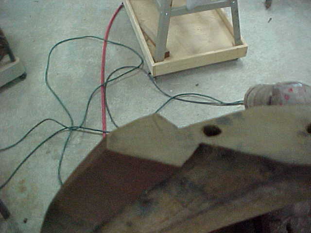
view of removed shaft log showing wear from improper shaft alignment
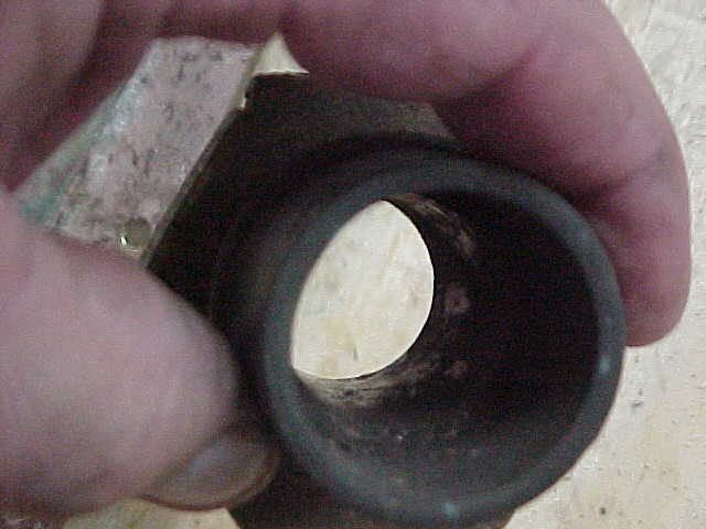
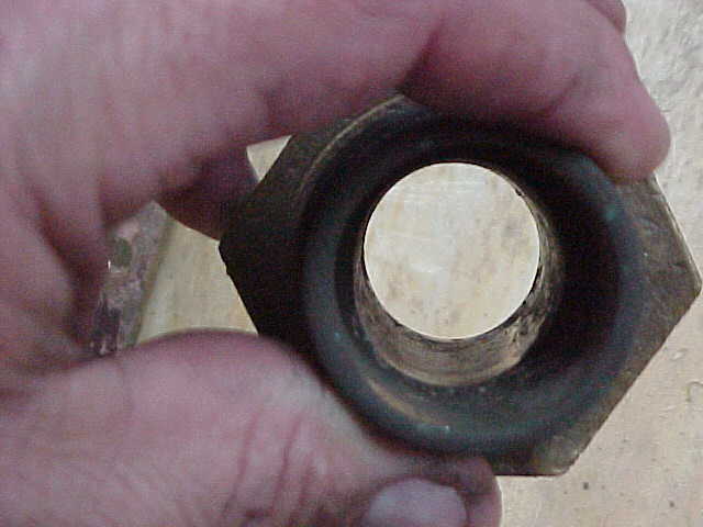
packing gland showing wear from shaft, arrow shows normal thickness of collar
wear in flange showing wear from shaft, see arrow
another angle showing wear in gland from shaft
Packing in shaft gland showing well packed and aged packing
other end of packing gland showing packing tight inside
shaft log showing wear from improper shaft alignment
another view of log showing wear from shaft
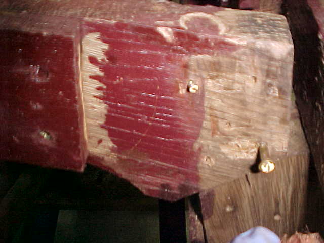
closeup of shaft log showing wear almost completely through wall due to shaft alignment
again, view showing amount of wear from bad shaft alignment
side view of aft piece of keel removed
view of keel showing shaft log removed, not very little sealant under flange
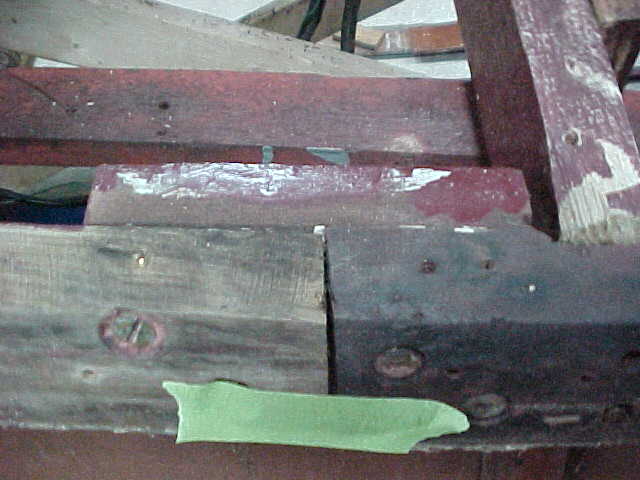
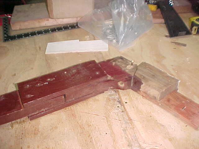
view of keel showing improper splice which can cause leakage between the joints, weal joint and flex.
wear is almost completely through wall
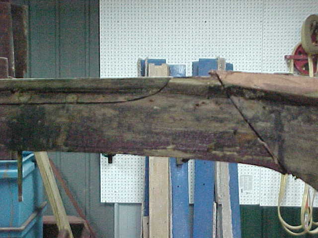
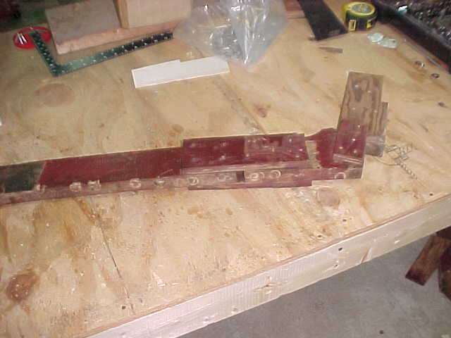
view of keel joint under engine, approx 18in long with 45 degree joint which is a weak link in old keel
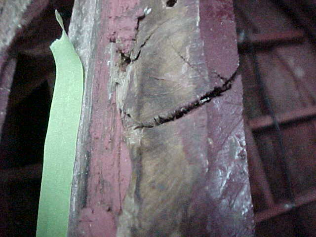
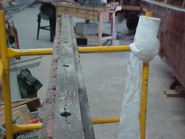
old keel front showing decay
another section of old keel showing decay
mid section of old keel with cracking and decay
another view of old keel with same cracking
note long crack in this piece of keel
aft section of old keel with wear and decay showing
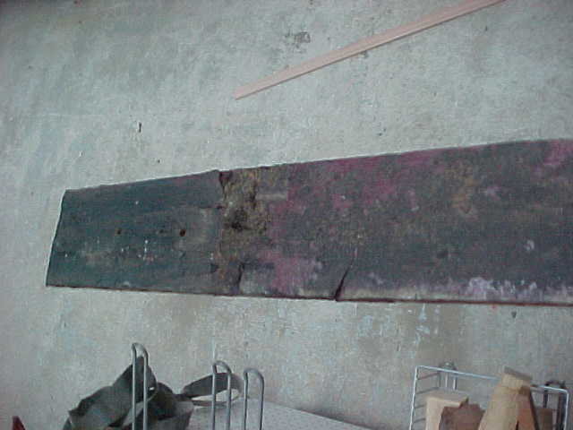
old keel laid out on scaffold to view
In the pictures above we show a worn shaft log which was caused by several factors. One was improper alignment and the other was no support under the log area with the framing. Also, we show the old keel with joints of 45 degree splices which leaves a weak connection and allows water seepage and flexing. We will replace the keel and the splice will be no less than 60 degrees . This is determined by the thickness of the wood. We will also put water stops in the joints to prevent any weeping of water through a seam after it is installed and 5200 applied and screwed and bolted down. As you can see we leave no stone unturned looking for any damage and preventing any in the future therefore protecting your investment for many years to come.
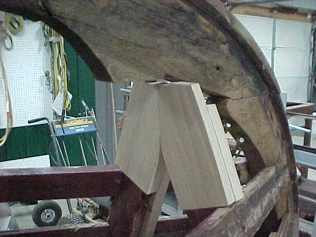
Bow knee, frame 1a and 1 without keel
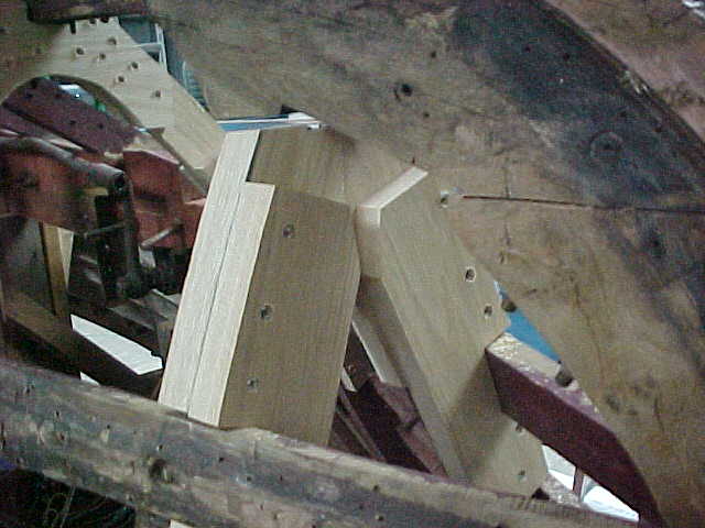
bow knee showing miss matched cuts on both sides where side planks come to bow
close view showing the mismatched cuts on bow knee
12
13
1/25/10
4/14/10
7/14/10
From time to time throughout a project it is prudent to increase insurance values.
These pictures have been taken before painting of the bilge and are to show the insurance company all the new frames, new keel, and new chines. All the light colored wood in the boat is brand new. INCLUDING a new 5200 bottom made with new 1/4" BS1088 marine plywood and new 1/2" mahogany planking bonded with 3M 5200!
The pictures below show the new planks on the hull sides. Also note the ENTIRE hull has been refastened, re bunged and faired. New planks are shown with a red arrow.
New planks are shown with red arrows. The port side has matching new planks and chine cap
Behind the new transom is a new transom bow and extensive repairs to the transom framing