| ||||||
1956 Custom Build
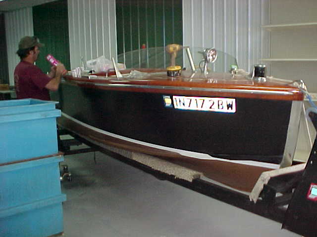
Scope of Work to be done
- Secure fuel tank
- Take to lake - Run engine - check its condition
- Perform Yard Survey - especially check condition of hull
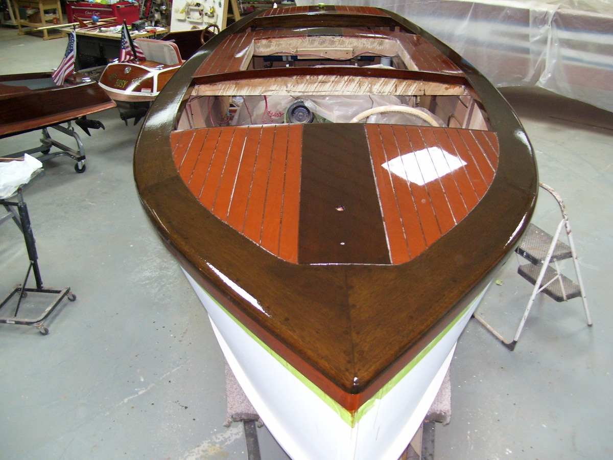
- Replace plywood (simulated caulked decks) with Mahogany Decks having routed and live seams. Strip remaining deck of finish. Sand, stain, seal and varnsish with 9 coats of varnish, then pinstripe white deck stripes
- Sand according to paint manufacturers recomendations and apply two coats of Hard Antifouling Copper Bronze bottom paint
- Fair sanding divots out of hull sides and re-coat with top side paint for smooth and glossy appearance
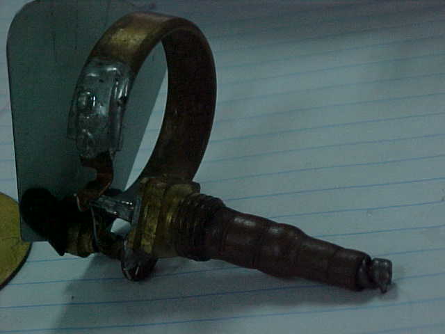
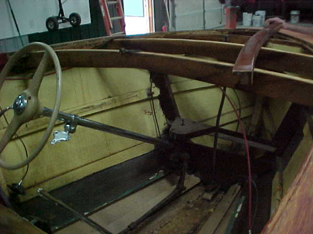
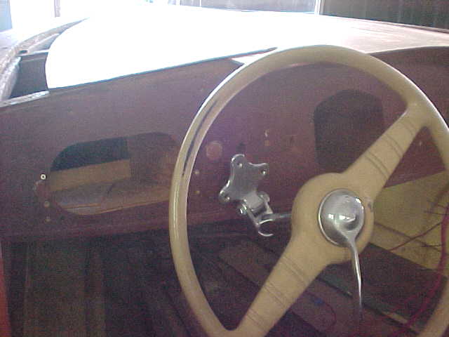
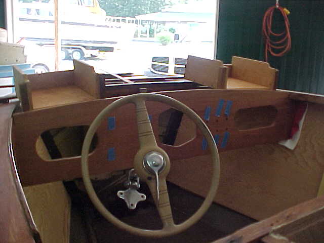
- Repair original Throttle in center of wheel - bypass linkage and install cable from bottom of throttle control lever to carb.
- Replace Steering Wheel with other vintage correct steering wheel with no throttle
- Note to owner. Consider having us get the original period correct steering and throttle combination working properly.
- Replace Dash with either brushed metal or varnished wood dash complete with glove box with power outlet.
- Install CD and speakers in an inconspicuous manner
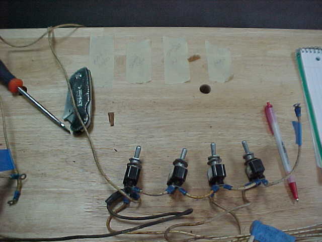
- Purchase and install new / proper push pull switches in dash
- Install engine complartment ventilating fan in inconspicuous manner
- Possibly remove spot light and replace with air horn.
- Sandblast and paint coat trailer, replace wheels with aluminum (possibly bronze anodised?) and add bronze pin stripe to trailer... or source new aluminum trailer
- Improve legroom in rear cockpit
- Re-rout exhaust below back cockpit floor
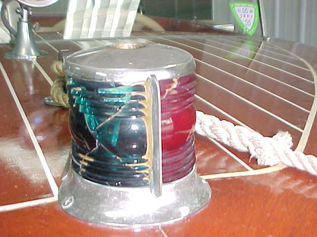
- Replace broken lenses in Bow and Stern lights
- Tilt Seat(s) Back for more comfort
Update 10/09/09
Yard Survey
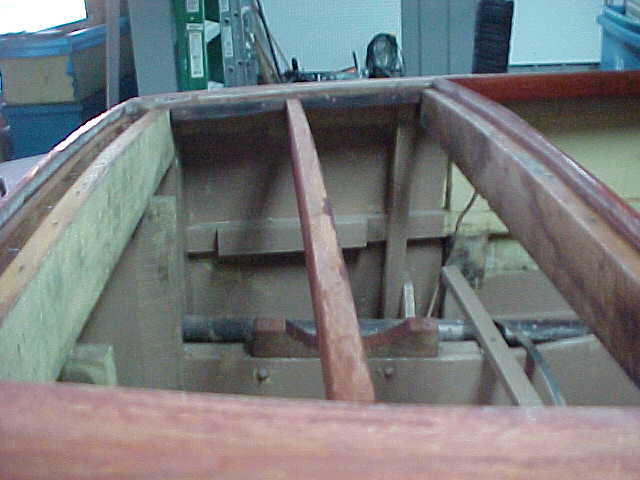
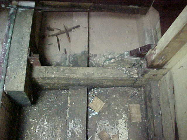
The below pictures are of the inside prior to dipping for leak detection.
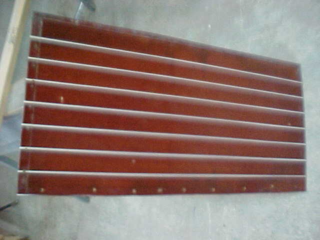
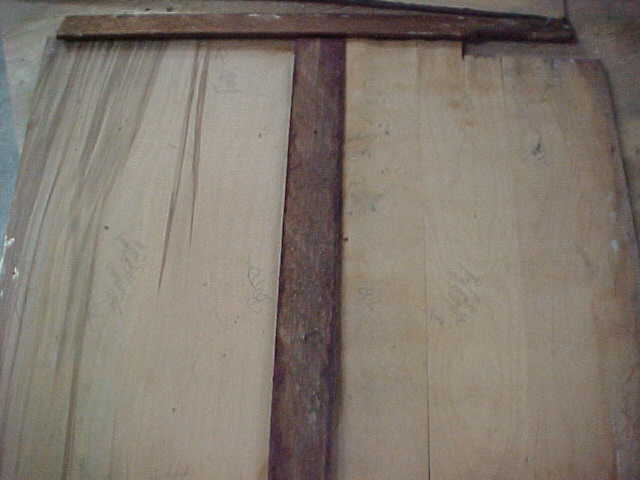
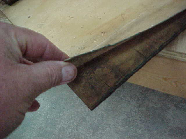
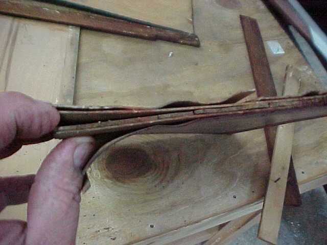
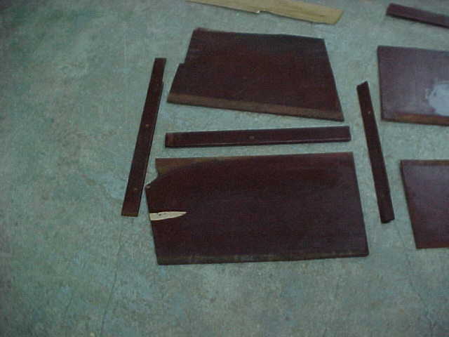
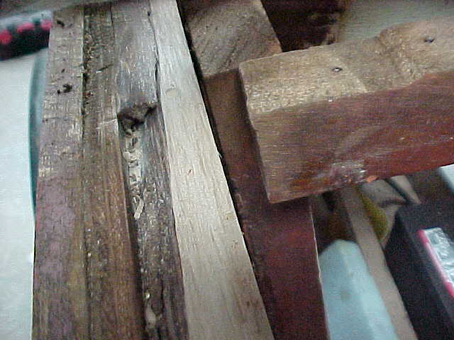
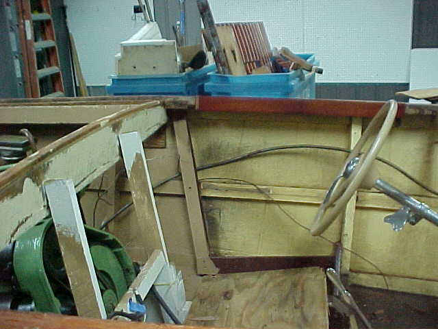
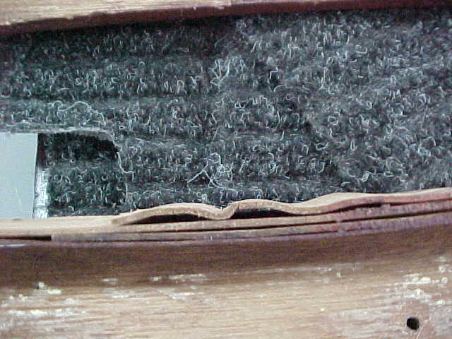
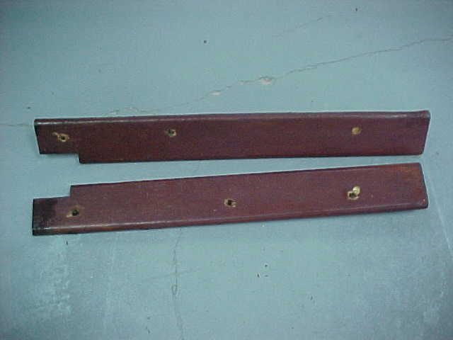
The pics above shows some trim boards from the port and starboard sides aft of the engine compartment
that are delaminating as they are not marine grade plywood
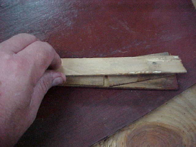
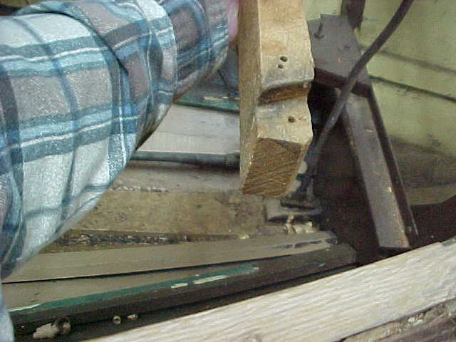
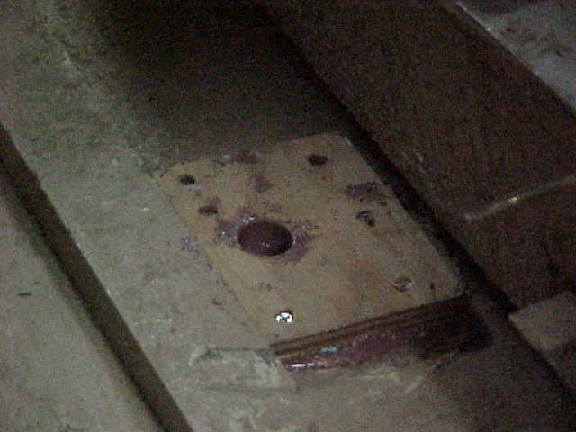
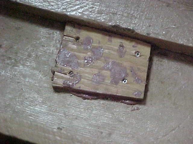
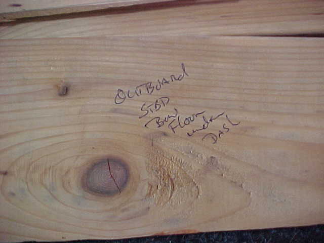
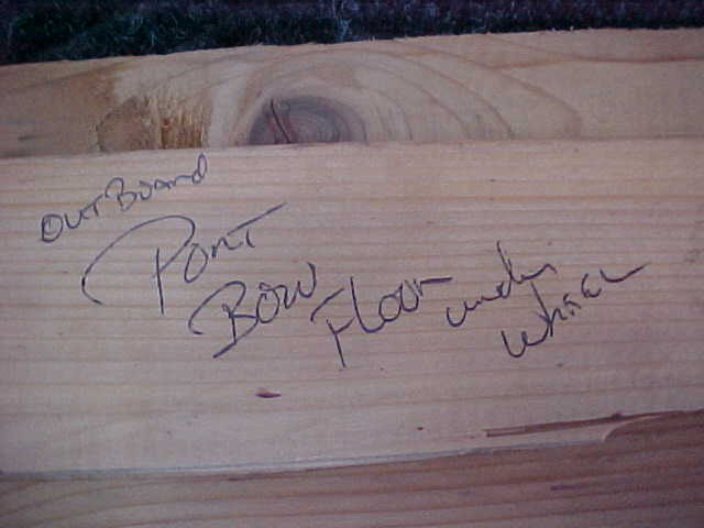
Above pics are boards found used as filler to support port and stbd floorboards in cocpit on outbard sides
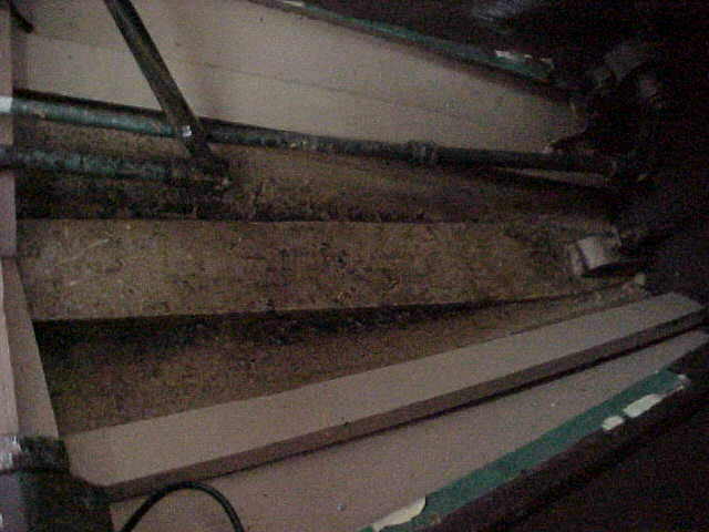
aft compartment port side bottom
Trim from aft compartment outbard sides, fwd edge
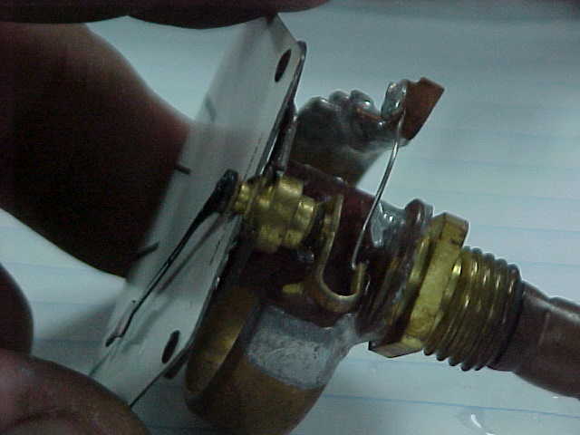
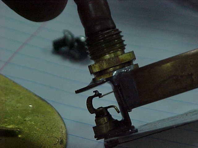
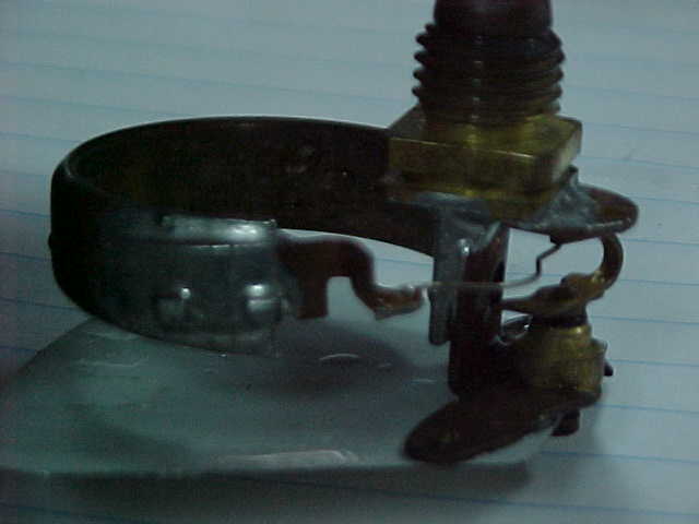
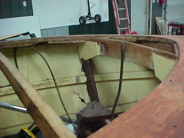
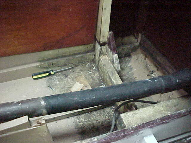
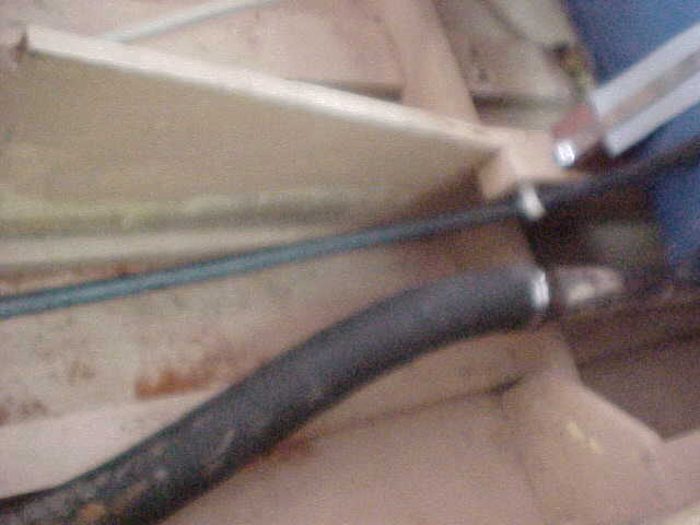
Forward bottom keel at bow showing shift linkage
Aft compartment starboard side botom
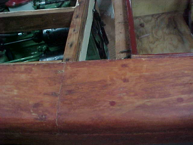
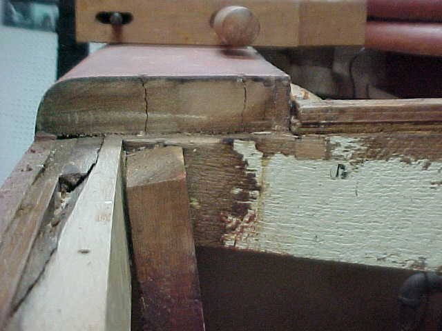
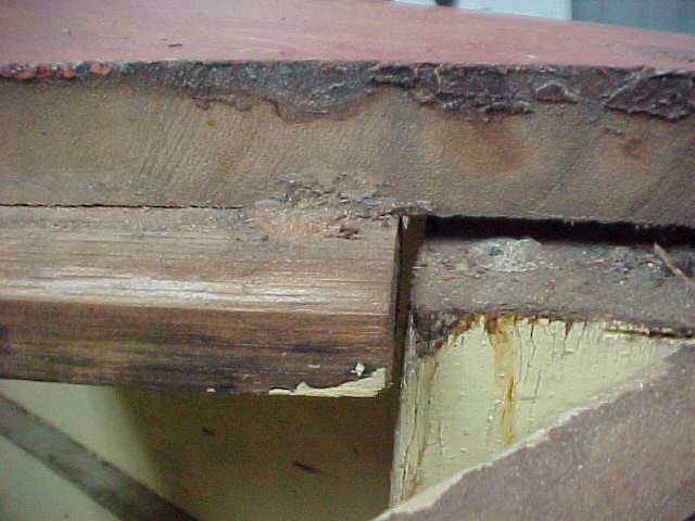
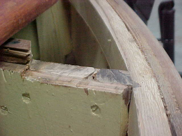
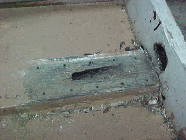
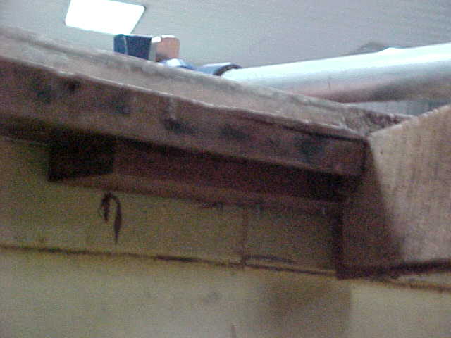
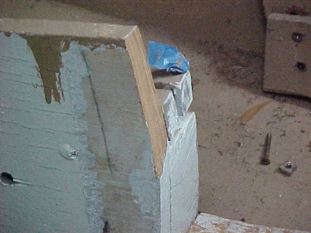
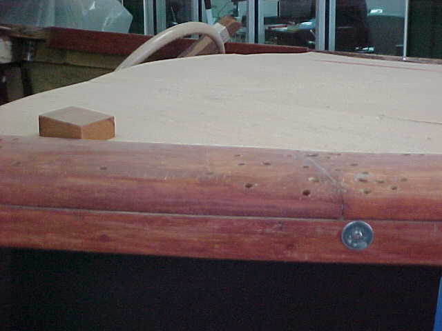
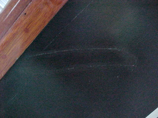
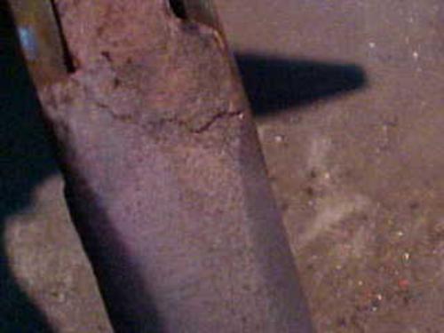
Starboard side below caprails at cockpit showing
a gouged area that was repaired but needs to be repaired correctly and blended prior to new paint.
Update 10/15/09
Yard Survey
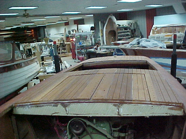
left, engine hatch, stbd side after removal, to be replaced with mahogony plankng
close up of same hatch as above, to be replaced with mahagony planking
opposite side engine hatch removed, to be replaced with mahogony planking
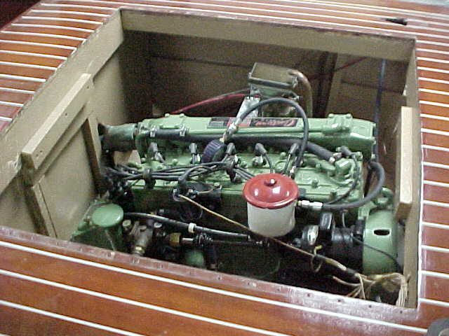
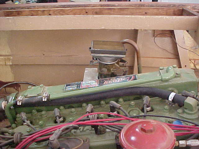
engine in process of comprression testing
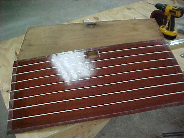
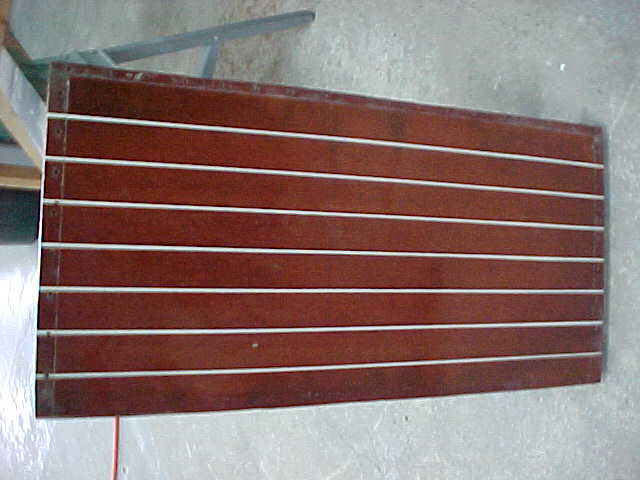
old port engine hatch panel
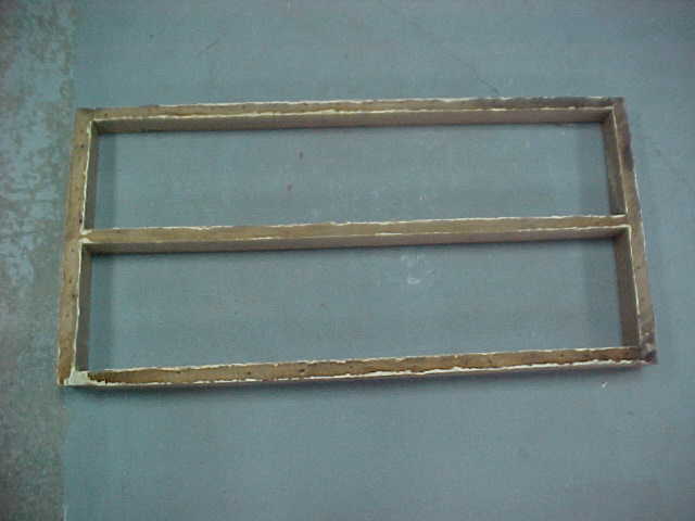
frame work for engine hatch to be worked and reinforced
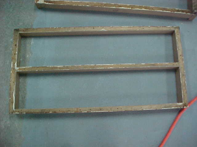
opposite engine hatch frame to be reworked, reinforced
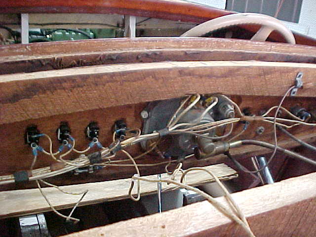
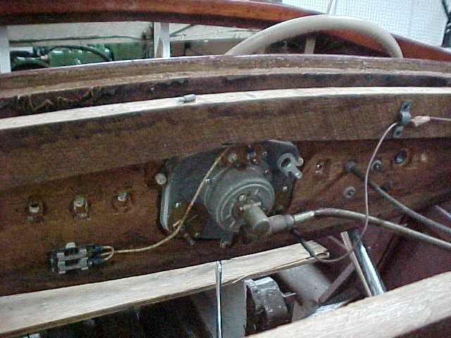
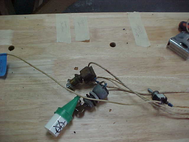
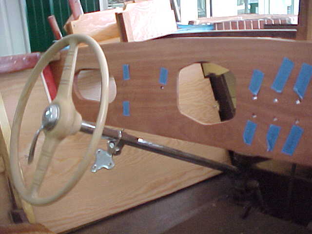
pic of original dash wiring, to be redone new
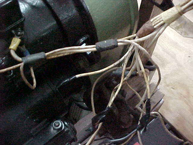
old wiring at generator to be replaced
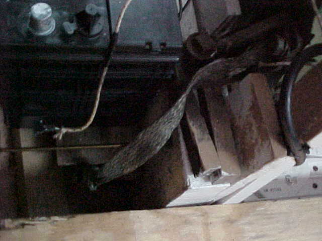
grounding strap on front of engine to replaced with new cable
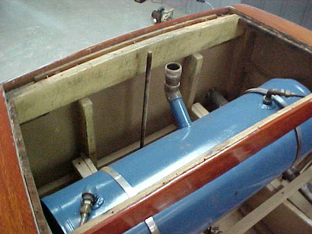
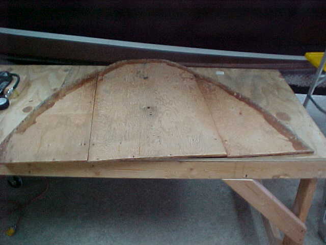
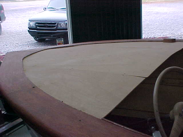
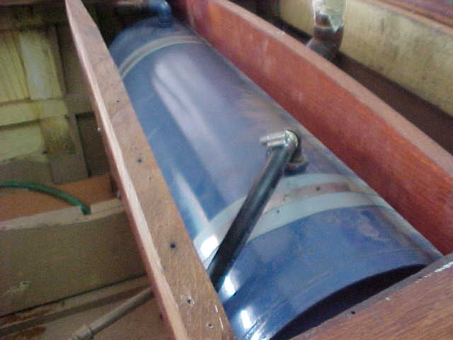
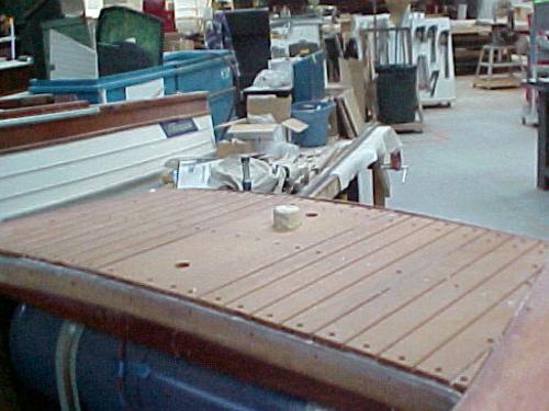
aft decking area removed showing view of gas tank. We will be adding blocks under tank or support and reworking decking and framing, decking will be new mahogony plankinf.
old front deck panel support plywood sheathing.
engine run for survey
Below are pictures of inside trim panels from the sides of the boat at the engine area and cocpit area on starboard side
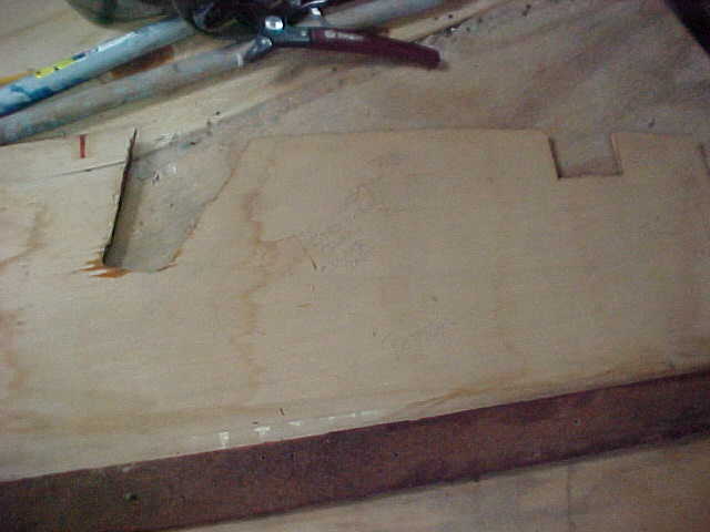
old side panel roughly notched to fit
old side panel from engine area
old side panel from stbd cockpit area
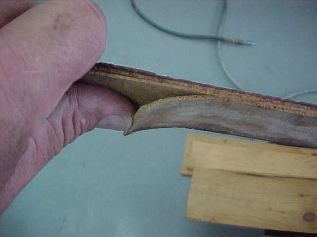
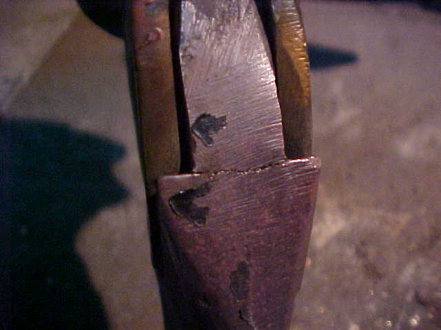
old piece of trim showing delamination of ply
old piece of side panel with delamination of ply
delamination of plywood side panel
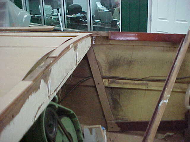
back side of dashboard with wiring and switches removed
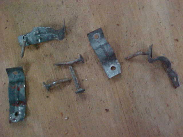
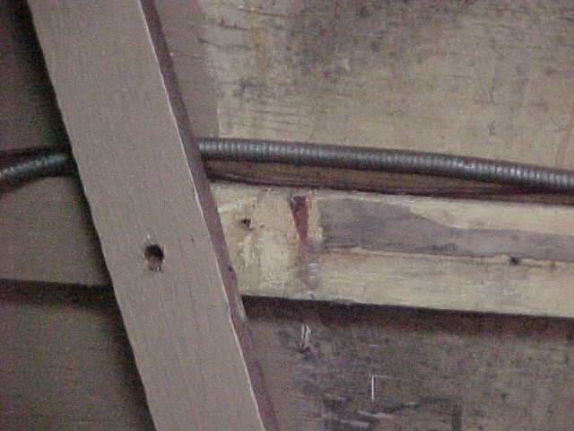
This shows wiring harness attached to framing with roofing nails which are rusted
another metal strap holding harness and showing rust on the roofing nails and strap
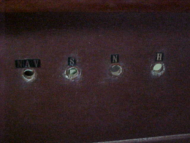
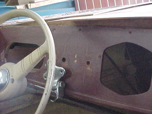
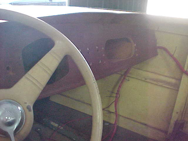
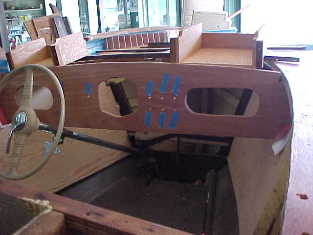
these two pics are of the dashboard showing location of removed switches
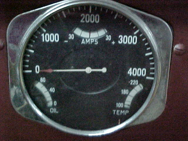
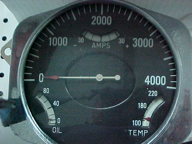
picture of Tach showing oil,temperature, and amps guages
Out with the old, make room for the new
We are beginnning to remove old pieces and catalogging so as to maintain a record of work accomplished and to show condition of old boat versus restored boat later.
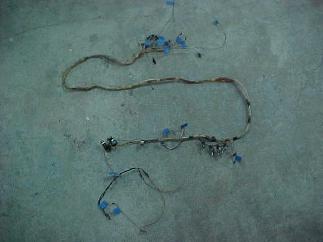
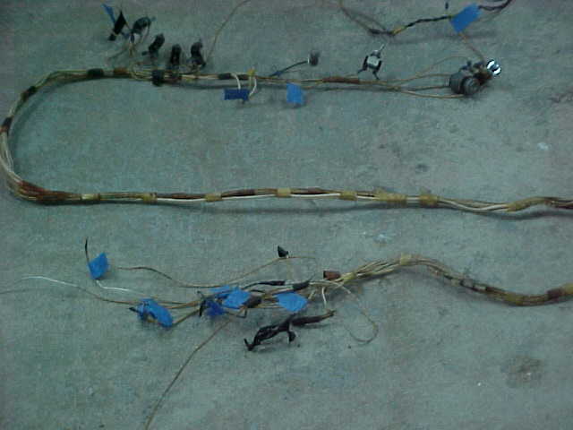
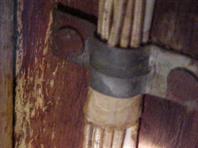
These two pictures are of the original wire harness from the console to the engine, lights, horn, generator, coil and other electrical components. We will use this as a sample to manufacture a new wiring harness and install with proper hardware and protection.
below are metal clamps and roofing nails used to hold wiring harness to the framework of the boat, which was rusting and would have lead to rot and mold of the wood around it.
270-866-2628 Paul@woodiesrestorations.com
New Toll Free Phone Number 866-921-2628
Below is close view of old temperature guage workings
side close view of internal workings of old temp guage
above is another view of workings of old temp guage
Left is view of guage cluster with tach, temp, oil and amp guages
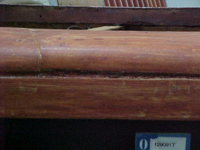
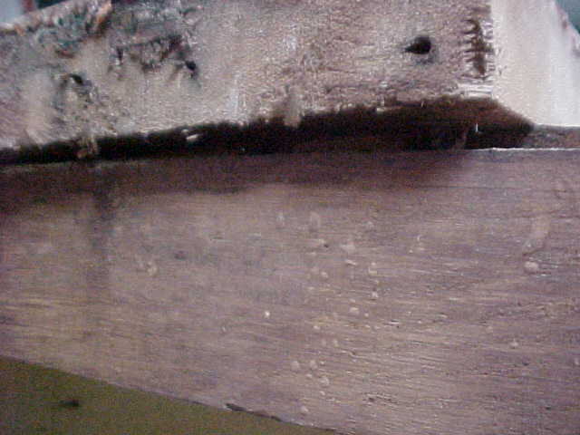
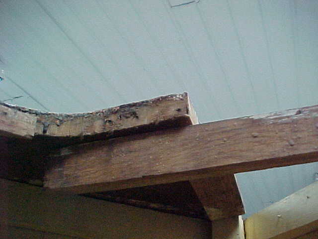
port caprail just forward of cockpit showing some separation and filler. Just after stripping.
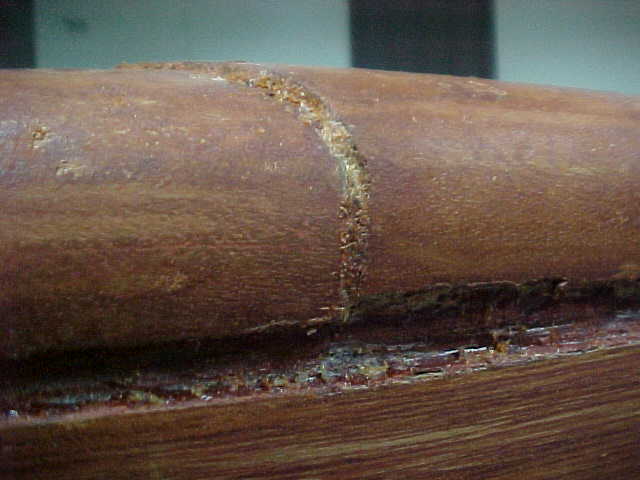
Above is the starboard caprail just forward of the cockpit show major seraration and cosmetic filling. This is to be lifted, cleaned , reinforced as necessary and pulled back into place. This also shows lumber without the varnish, just after stripping.
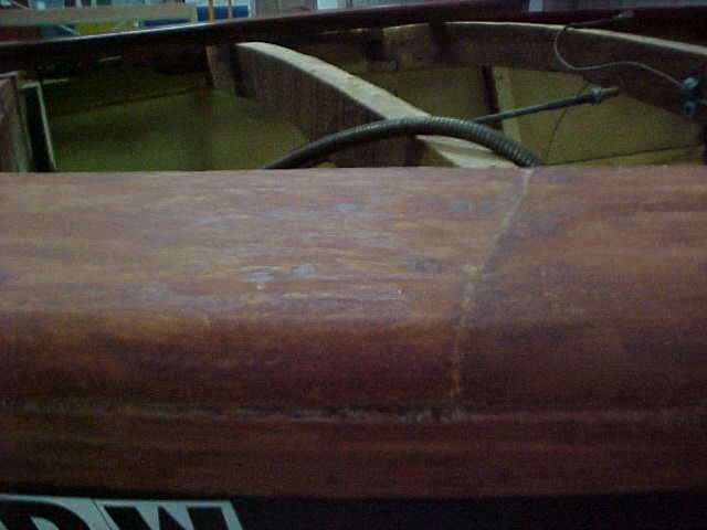
above and below is starboard caprail after finish was removed
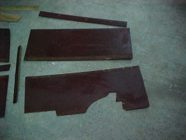
The three pics above left are of the inside cocpit panels removed and showing delamination of nonmarine plywood. These are to be replaced.
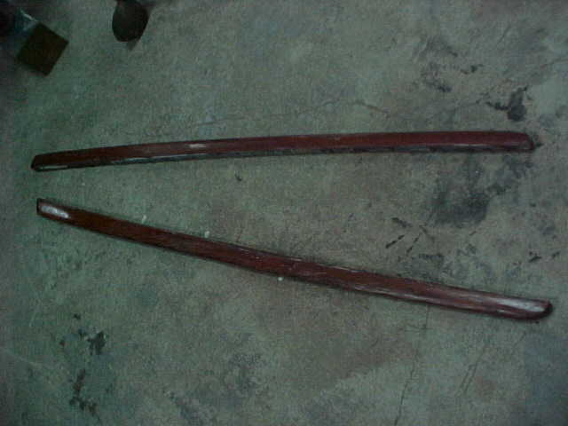
Below are the two rear sprayrails removed which will be cleaned and replaced.
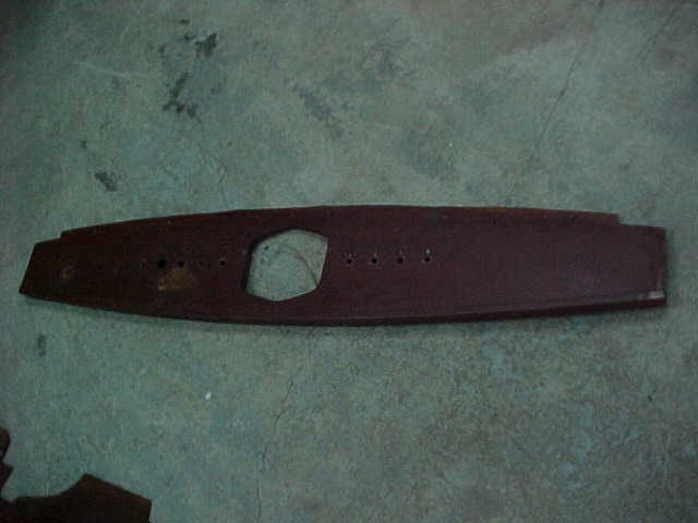
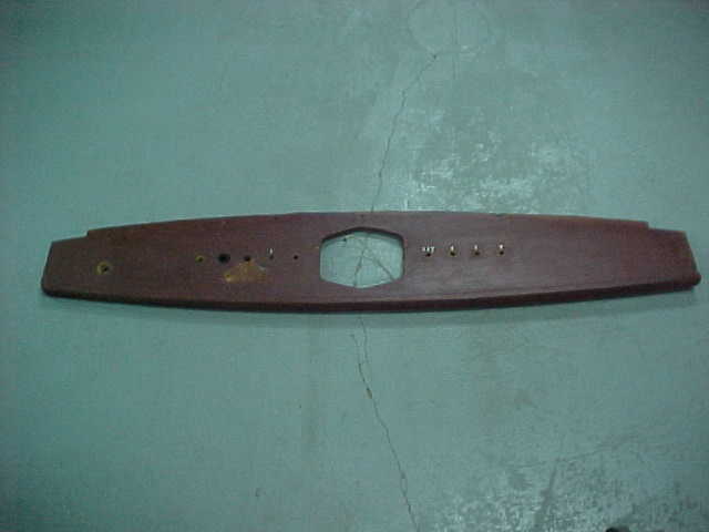
above is the old dashboard removed and to be used as a guide for new dash.
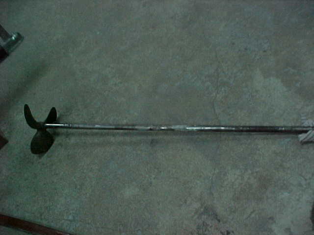
prop and shaft removed, to be cleaned up checked and reinstalled
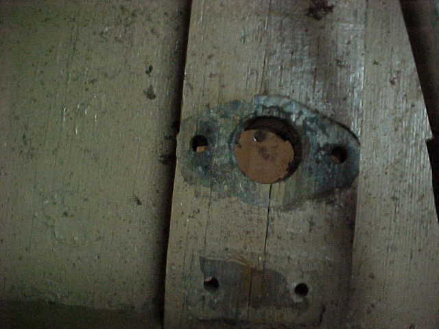
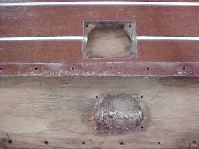
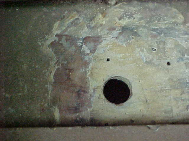
above is hole where rudder shaft comes thru boat and below it is the spot where lifting ring is attached. They are removed and will be cleaned or just replaced as discussed with Paul and yourself.
Oh No!!! It's all gone but no worry mate, it will be put back better than before. Cocpit area with dash, side panels, forward deck and floor board gone.
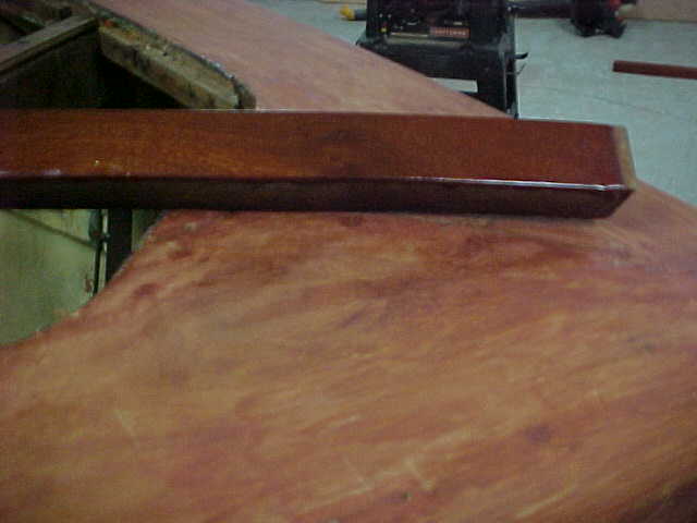
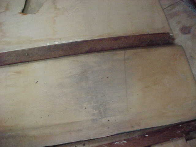
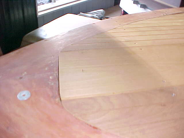
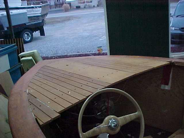
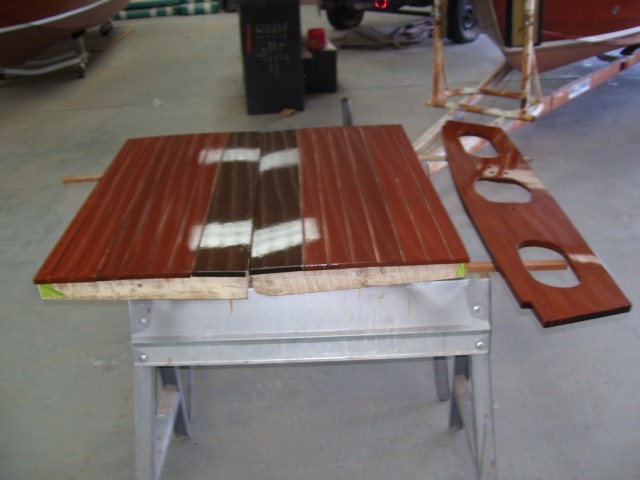
Nice pic with a piece for compariso of before and after varnish is removed. This is the nose area top deck
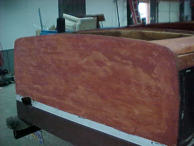
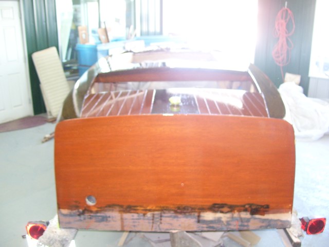
above is the stern panel with varnish stripped away.
Above left red triangle shows cap rail stbd side which will be removed to see why it has pulled up from the framing and what needs to be done to secure it properly, so as to prevent lifting in the future.
port storage compartment
stbd CD player/storage
port storage would be appox., 10" wide, 4" high, 8" deep
stbd storage would be appox. 12" wide,4.5" high, up to 10" deep
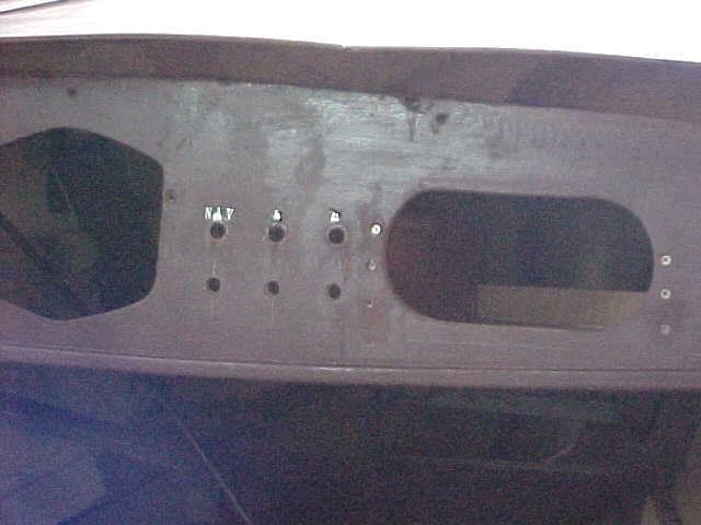
start button
IGN SW
choke
bilge pmp
nav lght
search lght
anchor lght
horn
tach cluster
Above is an idea of how the dash could be set up. If there are any suggestions please feel free to reply via email or phone to discuss. Port storage could only be 8 inches deep due to cables coming into dash from this side. Starboard compartment will be larger to accomodate CD player, which we need to know ( single or multi disc). Idea of metal covering for dash good and would be appox same cost as wood finished, and also this era boat was known for upholstering dashes to match seats. Again this is options for you to choose!!!
I would sugget a hand held VHF radio versus installed as cocpit room is limited and need to add antenna to boat which may take away from it's looks.
Similated idea of dash setup/ awaiting input for final make
above pics show old switches laid out before new harness made
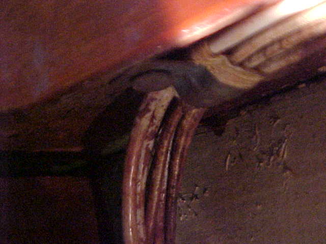
BELOW show attachment under bow caprails. No support, just connects pieces together.
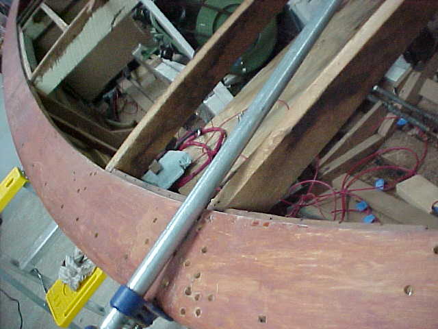
above is pic of aft stbd cocpit framework showing with arrow that there is no support for caprail on inboard half from this deck beam forward. Only support was other deck beams which were short and did not attach to topside framesor battens, just basically toed into bottom of caprails.
above shows piece toed into bottom of forward covering board, but not conected between port and stbd framing.
lower pic showes deck beam not extending from outside frame to frame, therefore no real support
above shows sheer clamp worked anddeck beam fitted.
above is fwd cocpit deck beam showing that it is appox 5 inches short from connecting to port and stbd framing, again, no support.
above is close up of deckbeam and sheer worked to fit caprails smoothly.
below shows where deckbeam should be, but orig. was 5 inches short of reaching both side framing.
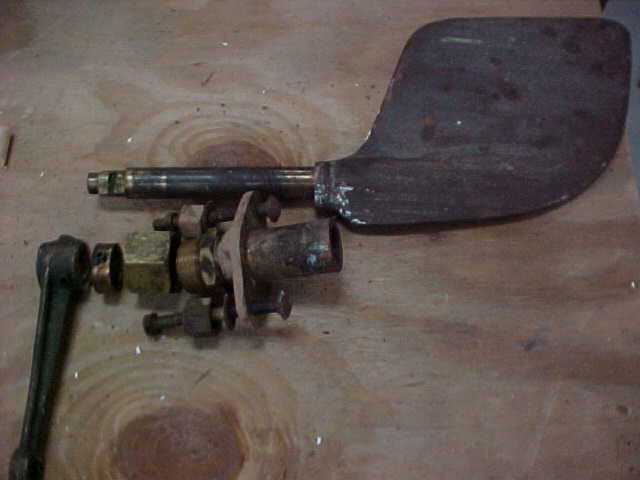
above is removed rudder, rudder shaft log, packing nuts, lock ring, steering arm and arrow shows oversize nuts used as spacers for thru hull bolts. We will rethread thru bolts and eliminate " spacers" , and seal all with 52 mil compound.
arrow shows filler and gap which will be removed and worked to fit properly.
arrow above shows board has no connection to framing and gives no solid support only used as batten for forward covering boards
arrow right shows covering board with batten under which serves no solid frame to frame connection
Which way do we go!!! Several options available for dash conversion, "but only you can decide".

aft deck support beam manf and installed temporarily
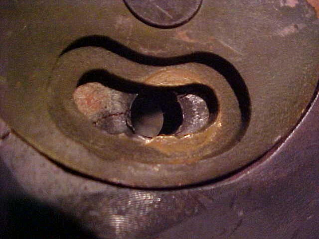
shaft log removed. No sealant on original and copperbronze screws bent/damaged and need replacing
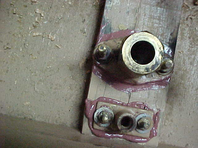
rudder log and lifting ring reinstalled and sealed with 52 hundred
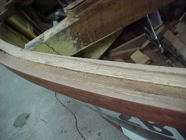
reworking fwd stbd caprails
new butt block for stbd fwd caprails
aft deck beam temporarily installed
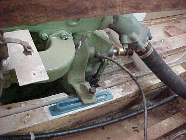
engine thru hull for water intake
gas tank support log installed
new underlay dor bow decking
new underlay for engine hatches
new thru hole for engine coolant
aft thru hull patch for old drain system
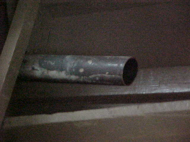
exhaust pipe behind rear seat cut off approx 2 ft
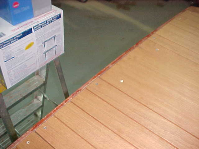
new stbd caprail work showing tight fit and underlay for deck
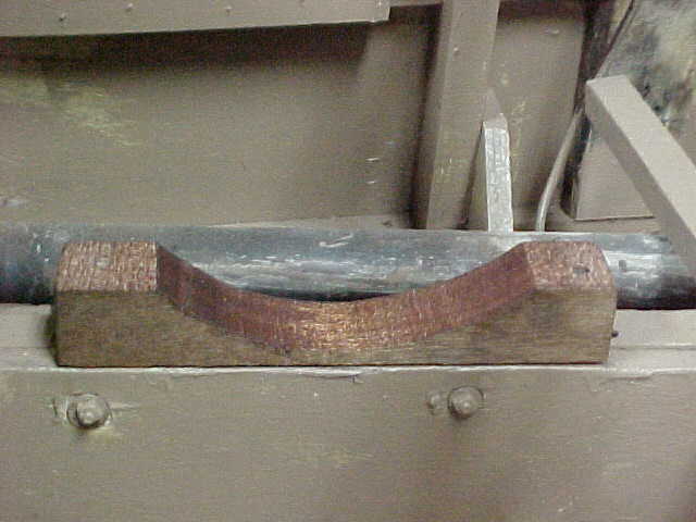
Bottom seat brace showing cut back to allow for more angle on seat
pic above shows where old seat position was and the new position it is in now
picture shows the seat back brace removed which eliminates the small deck area right behind the cockpit and between the engine compartment and seat back. Also shows relocation of side supports and shows new angle of seat.
Pic shows old seatback supports and side supports in original position. You get approx 3 inches of upper seatback recline but lose the small deck area between the seatback support and engine cowlings.
old deck area gone
shows new position
arrows show old and new position of seat supports
view of dash with port stereo box cut in
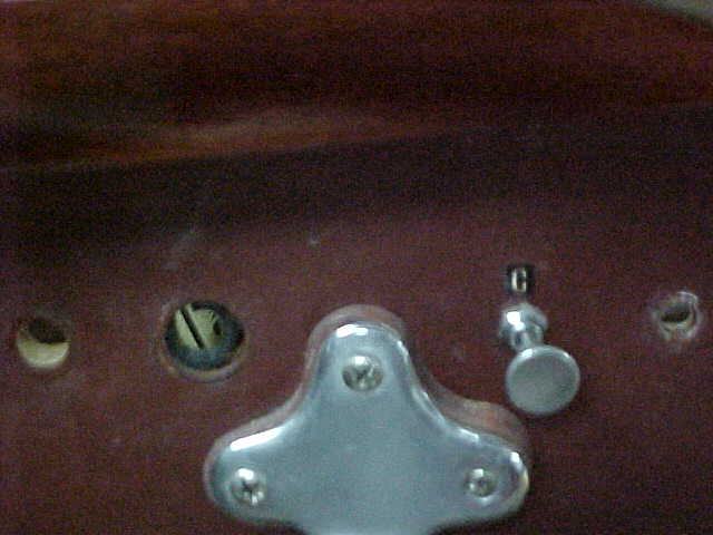
view of dash with stbd glove box cut in and new holes for switches in place
view of the stbd dash showing glove box opening
better view of port stereo glove box cut in dash
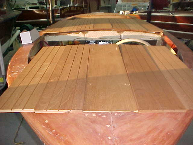
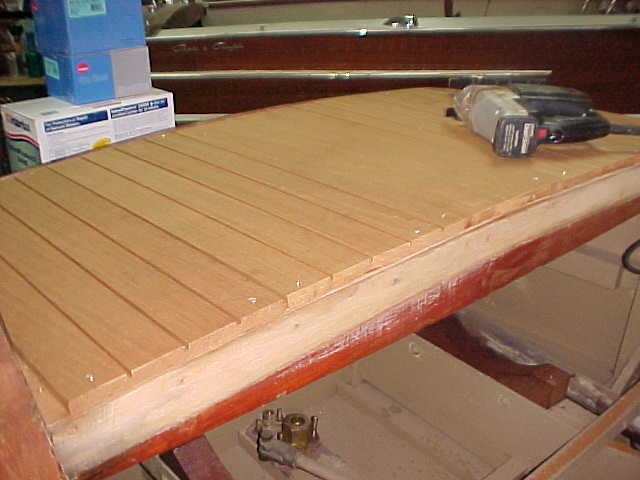
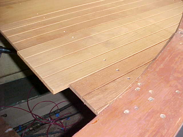
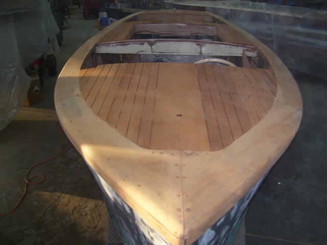
bow view of curfed decking trial fitting
another bow view of trial fitting
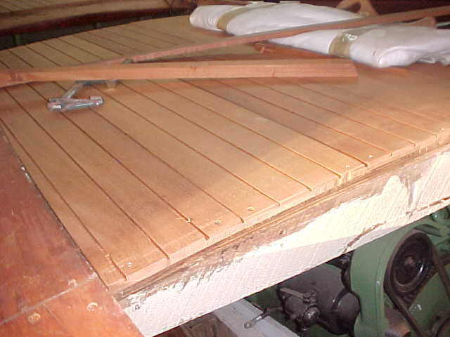
view of mid section curfed decking trial fitting
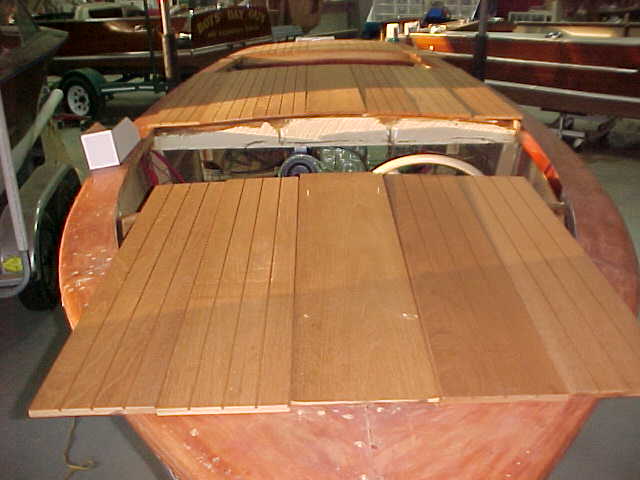
view from stern of aft decking curfed and fitted
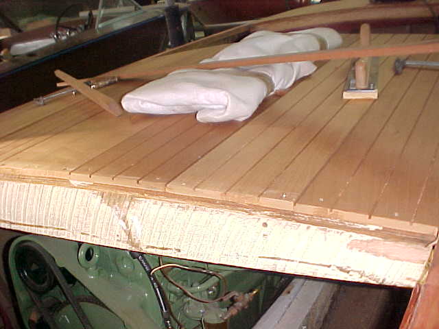
view of back deck edge fitting of new planks
view of back deck from aft compartment
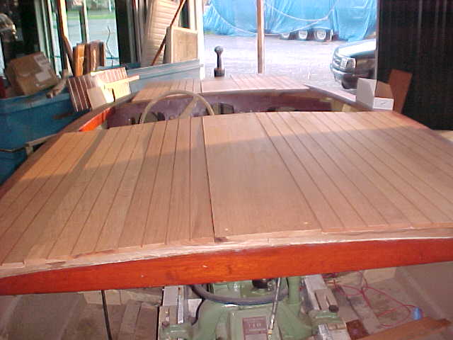
view of engine compartment decking from fwd compartment
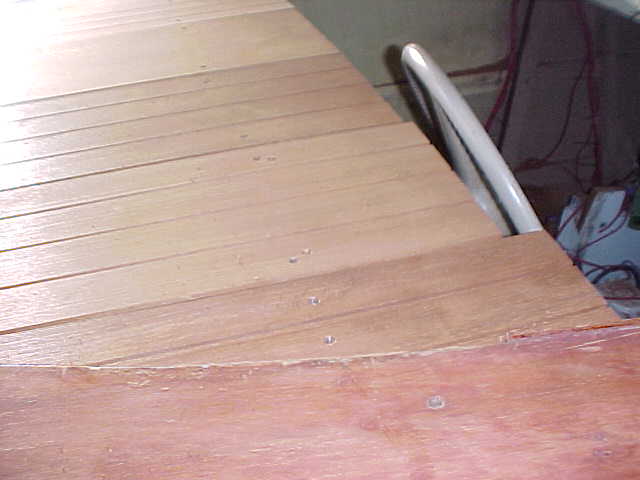
View of fwd deck stbd corner fitting
view of engine compartment fom aft cockpit
engine compartment decking from fwd cockpit
fwd port decking corner fitting
bow nose decking fitting looking from port side
new water hose top of engine
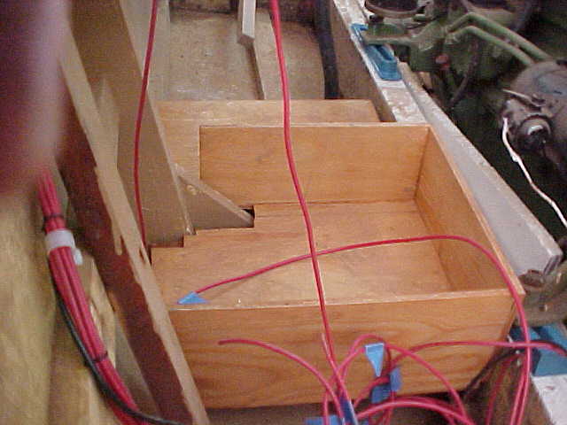
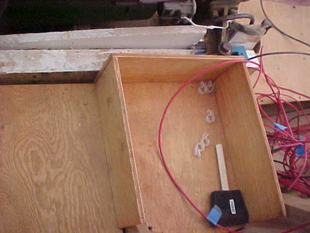
battery box/storage box in engine conpartment
new dash rough cut install for view also showing side panel
another dash view showing both side panels and new glove boxes on top.
view of new dashboard and glove boxes tobe installed
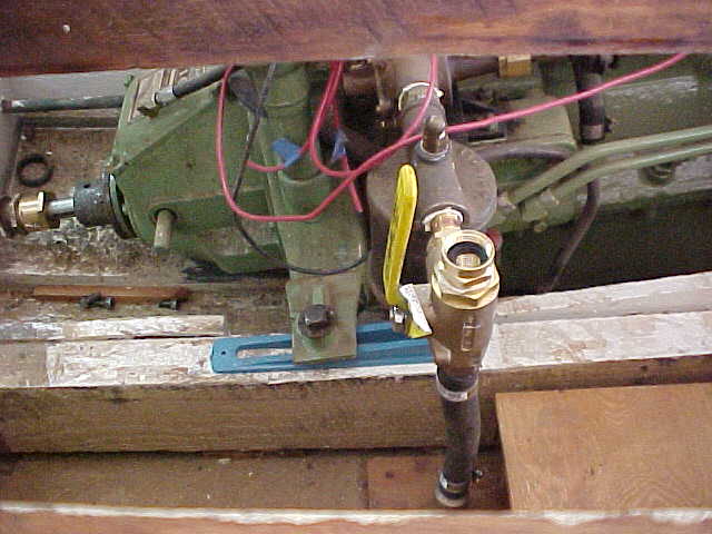
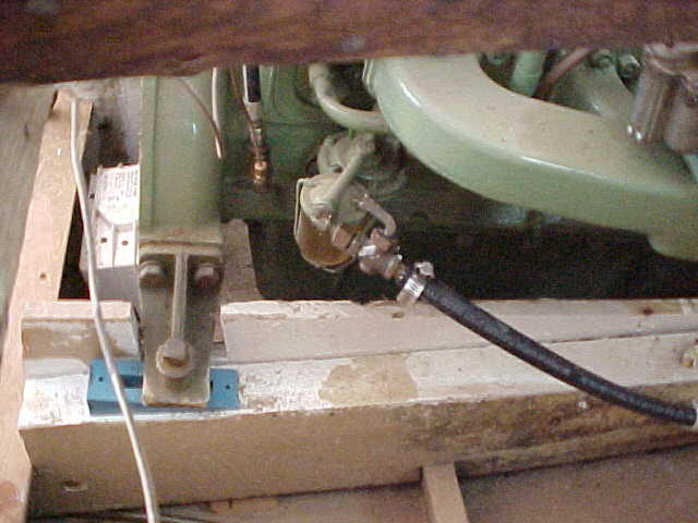
water intake hose,3 way valve installed
gas tank reinstalled and new hose connected
another view of battery/storage box in engine compartment
view of exhaust elbow reorientated,new gaskets made and new steel engine mount wedges
foward new engine mount and new fuel hose installed
rough picture of new exhaust hose run under floor board and fuel hos nex to it
made of 3/4 inch mahogany plank
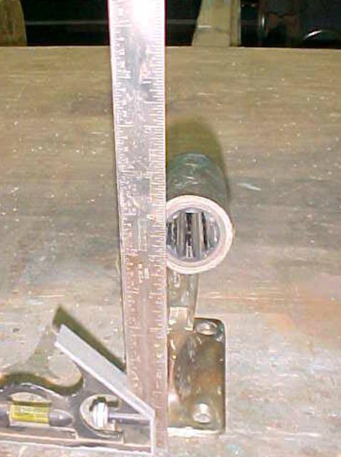
Picture to the right is of the shaft strut. As you can see it is bent with an offset of approx. 1 inch. We are attempting to straighten it out, other wise it will be an expensive buy. Keep your fingers crossed for a good fix!!!
Pictured to the right and below. Our attempt to heat and straighten the strut were not successful. All the stresses ended up concentrating on the joint instead of at the base of the strut where the actual bent area wasl. A new strut is on order!
Update 12/14/2010
In the next few days we are going to concentrate on
- lining up the engine and running gear.
- Landing the new wiring on proper terminals on the engine
- Landing the tach cable on the engine
- Making the liner panels that will go under the decks (this should be quicker while the decks are off )
-Installing the decks!
through the shaft log hole in the keel and properly installling the strut so that the shaft is not pushed up to, touching, and wearing on the keel. We have drilled and doweled the engine stringer today and moved the engine to the port about 1/4" centering the shaft in the shaft log. We then re-drilled the engine hold down bolt holes and installed. Next we moved to properly installing the strut... and found it bent. We also found the strut bearing to be nearly worn out and have ordered a new strut bearing.
Update 2/2/2011
Video Update filmed 1/21/2011
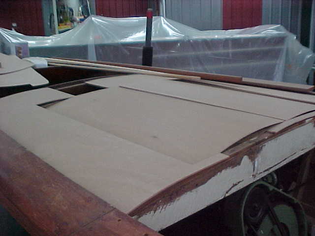
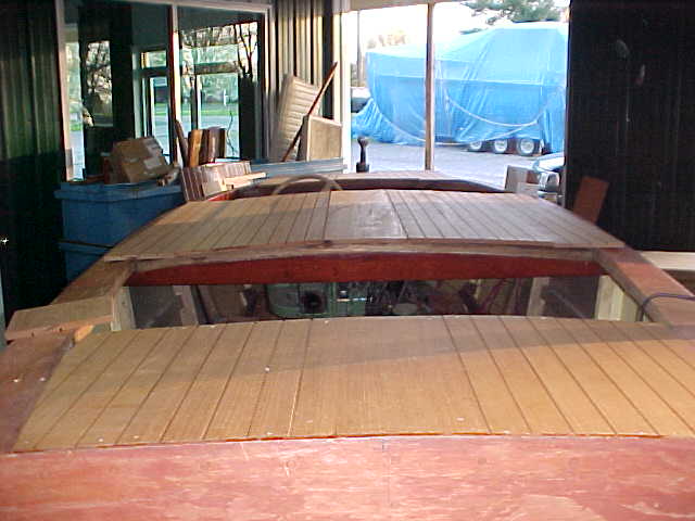
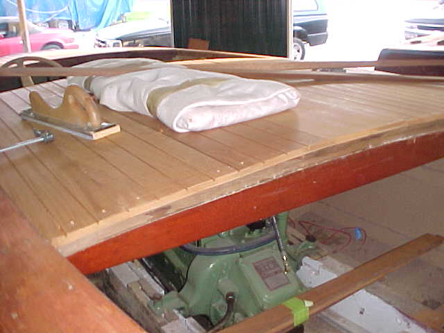
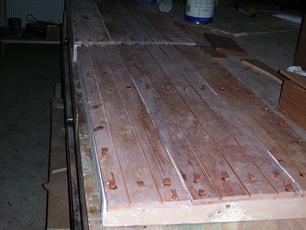
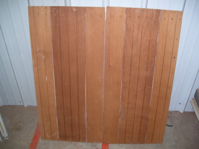
Decks look the same as before... but now they are fastened down bedded with 3M 5200 between the decks and sublayer of marine plywood. This layer will keep the decks stable and reduce their expansion and contraction thereby keeping deck seam maintenance to a minimum.
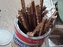
The engine hatches are sitting on the original frames and stops... which were none to correct. The hatches had to have been resting on their metal trim and hinges that surround the hatch covers. Some of that trim shows some bending occured. I think the trim is still usable after we do a little straightening before we polish. Small picture is of bungs in strip form that make them easy to install and orient grain. They are grouped by plank so they will match.
Update 10-28-11
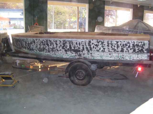
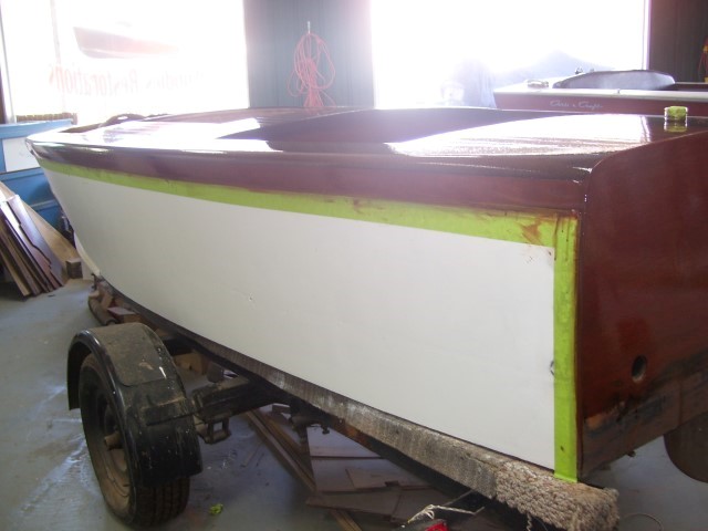
Sides have been sanded for primer. The dark spots are the low spots, light spots are the high areas.
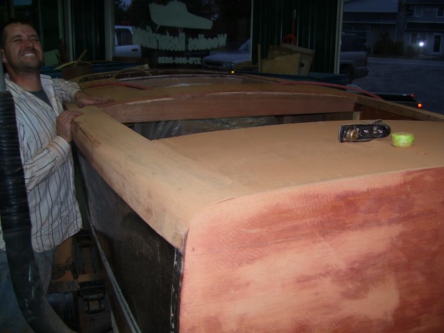
Decks and hatches are finished with the first stage of fairing. Now its time to sand out the cross grain scratches.
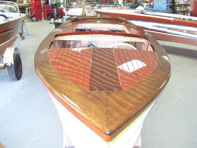
Chris Craft Mahogany and Walnut with 3 coats of sealer and 4 coats of varnish.
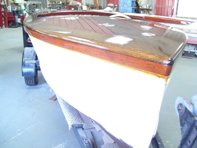
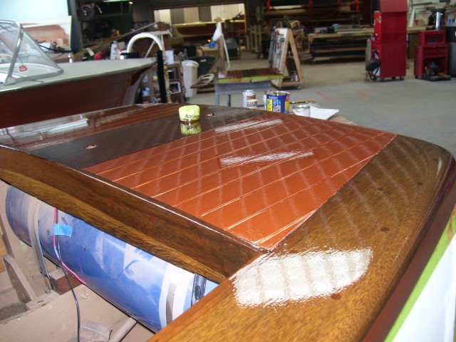
One coat of varnish after a good knock-down sanding.