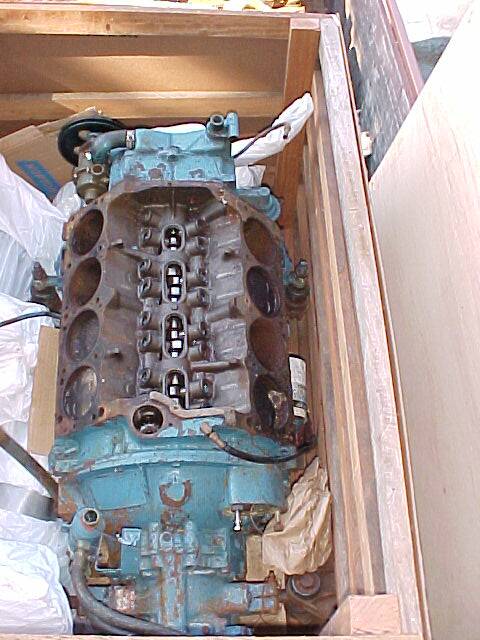
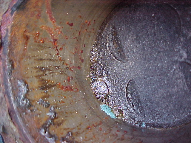
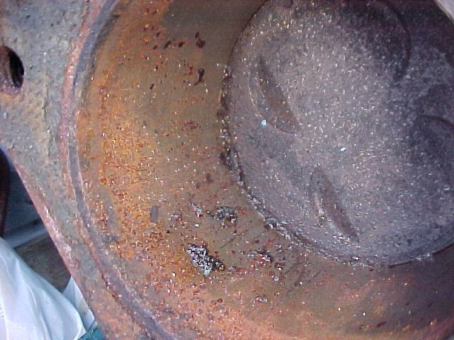
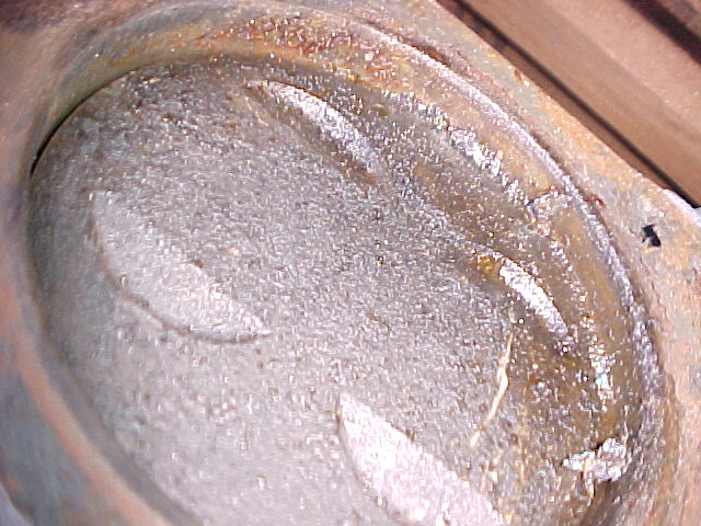
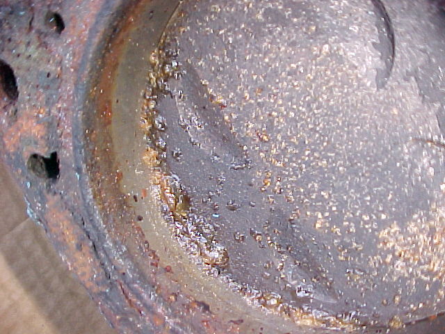
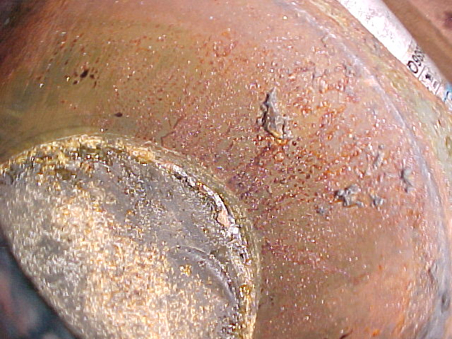
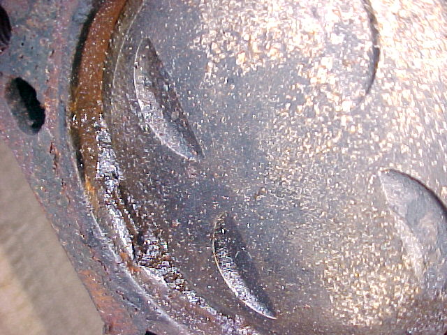
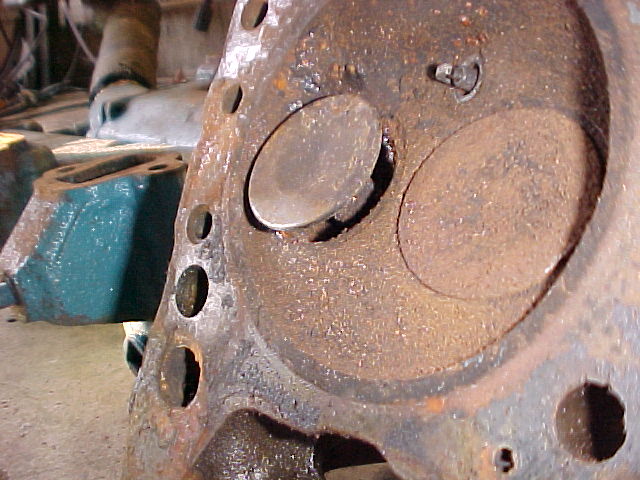
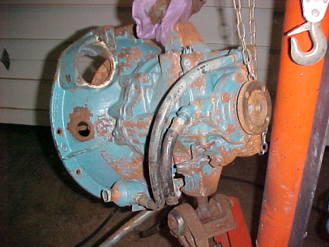
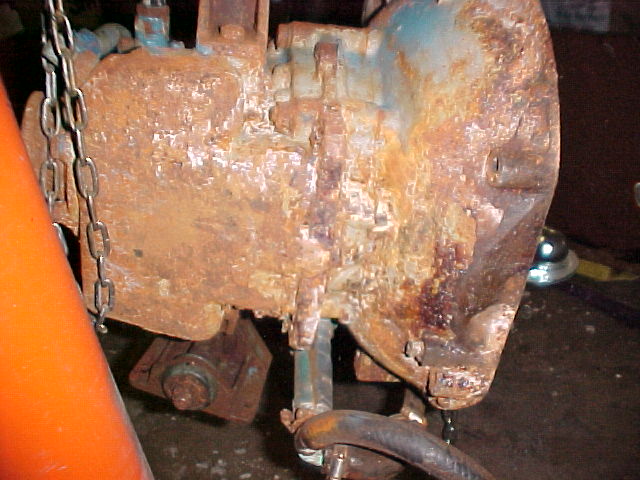
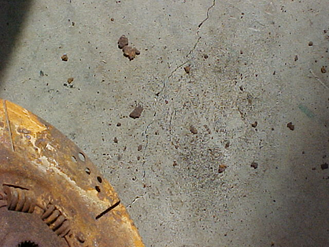
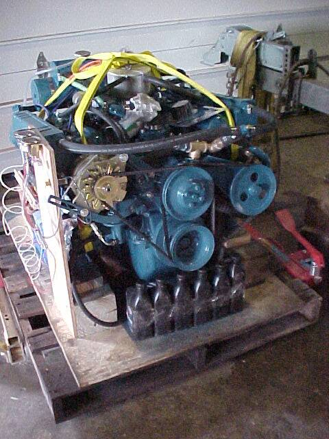
The engine evaluation began on Thanksgiving day - We can give thanks that the owner managed to get all the life the engine had to give before it began to fail! Note the condition of each cylinder... rust is visible where it has formed above the pistons. The data to support the need for rebuilding follows.... the headline is ... rebuilding is required!
The engine would not initially rotate. Presumably the piston rings are rusted to the cylinder walls. With a little oil a strap wrench applied to the crank shaft and a little elbow grease the engine rotated until the piston rings got up into the rusted areas but it would go no further.
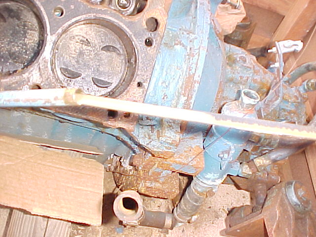
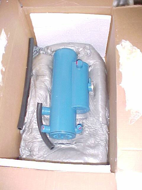
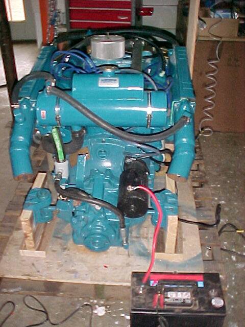
The engine - still in the crate is pictured in the center. Each cylinder was photographed and is pictured in its position relative to the engine block.
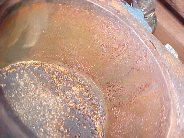
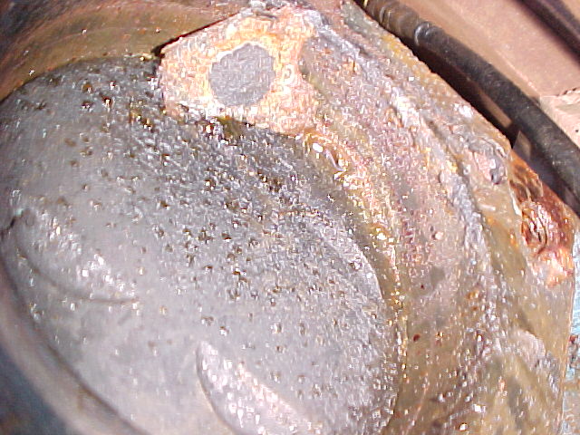
Pictured above is the oil dipstick. Note the dipstick tube to the left. The oil is light brown and milky.... meaning there is water in the oil. This may be adding to the force required to rotate the engine crankshaft. There is surely corrosion on the crank and cam bearing surfaces.
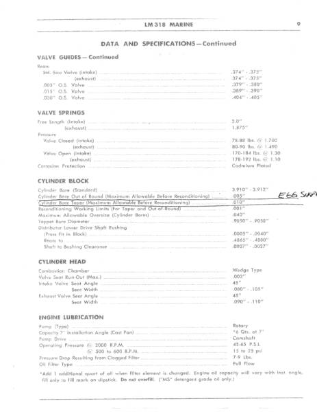
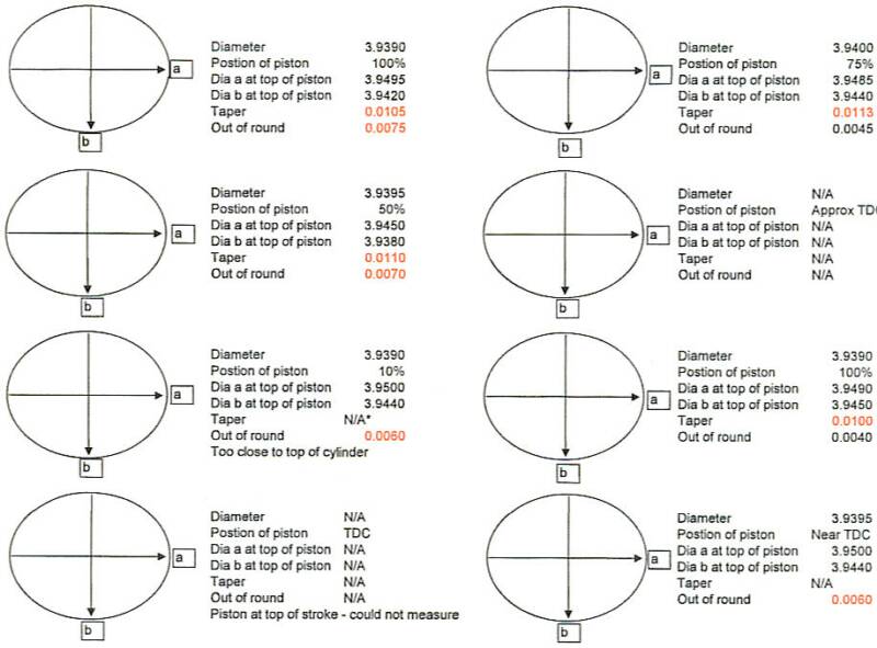
Above is a scan of the 250 page engine manual for this engine. The allowable taper and out of roundness (or egg shape) of the cylinder is shown in the specifications as .005" (5 thousandths of an inch) for maximum out of roundness before reconditioning, and .010" (ten thousandths of an inch) for taper. Note below the data indicates that the wear in most of the cylinders is beyond the maximum limits! Numbers shown in RED below indicate where cylinders are beyond recommended operating limits. Cylinders in which the pistons were too close to the top of the cylinders to get accurate readings are noted. Now that the engine has been rotated - these cylinders could be measured... but the data shows the engine clearly needs rebuilding so additional measurements are of no value. Note: this engine has been reconditioned at least once previously as the bore of the cylinders is .030" over the factory bore of 3.910" . (3.910+.030=3.940") The maximum bore allowed is .040 over the 3.910" or 3.950" Most cylinders are worn to near that maximum bore diameter.
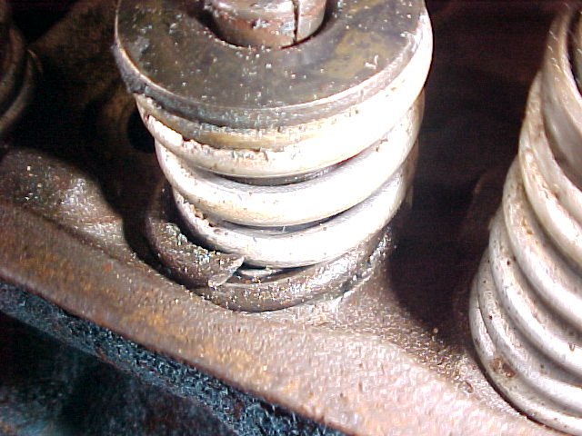
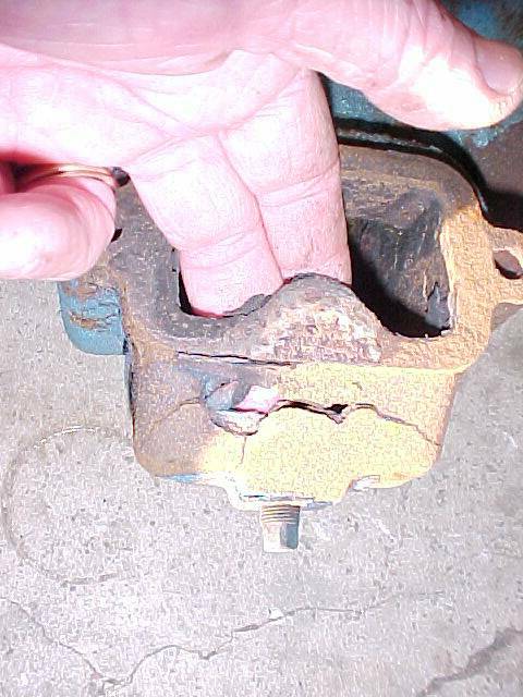
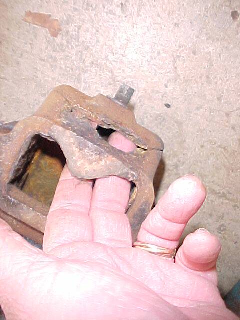
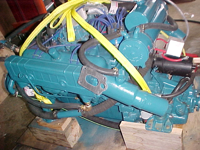
Turning to the Cylinder heads... this head has a valve stuck open. On yet another valve, the valve spring is broken. The cylinder heads need to be reconditioned.
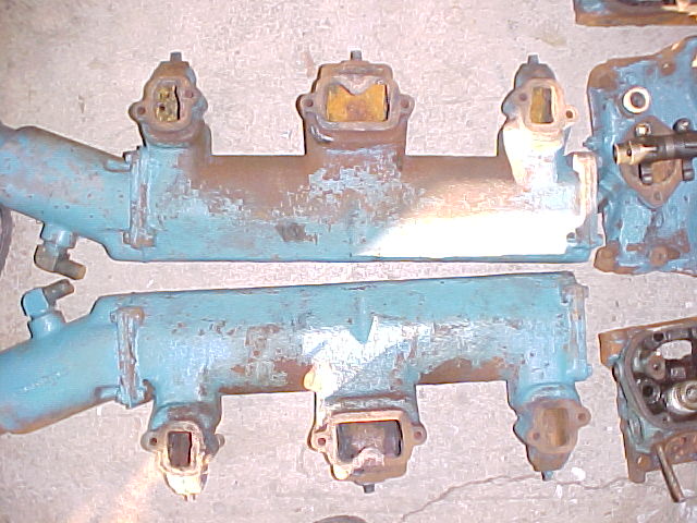
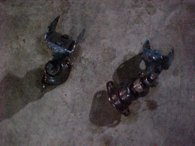
New exhaust manifolds will need to be located and installed. These are cast iron and not easily repaired. Due to the poor overall condition, repair is not a good option. These would soon rust out in other areas.
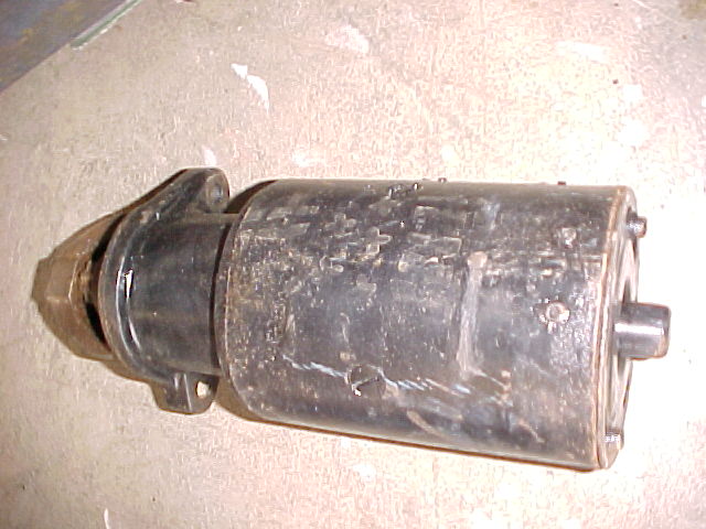
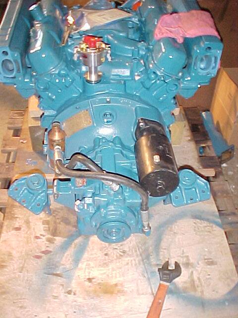
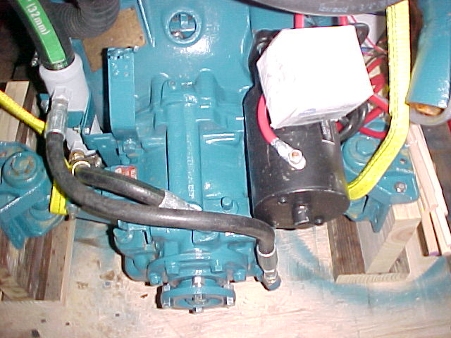
The starter was hooked directly to a fully charged battery and rotated very slowly. In fact it did not start or rotate forcefully enough to shift the bendix to engage the starter gear teeth with the engine flywheel. The starter will be rebuilt for many more years of service.
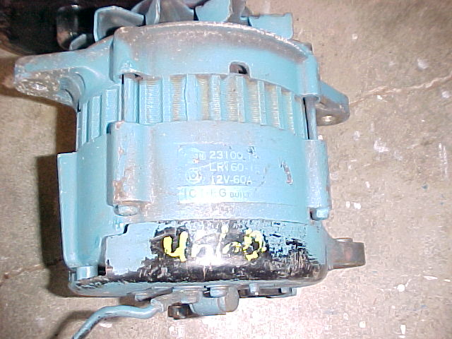
The alternator:
It appears the alternator is used. The yellow paint pen ink - commonly used in junk yards to identify parts is clearly visible. ...Gee, I hope new price was not paid for this alternator. Woodies will be checking this out further to ensure it is a marine (ignition protected) and not automotive alternator. If it is a marine alternator it will be rebuilt to ensure top performance.
/\
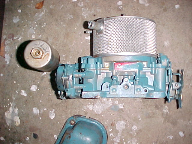
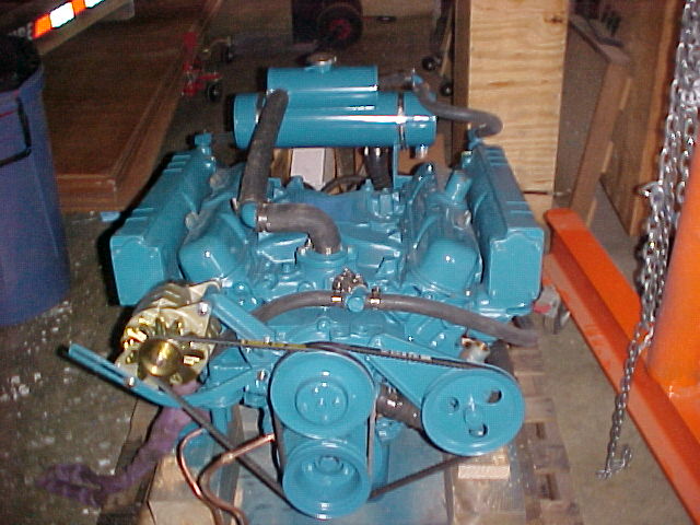
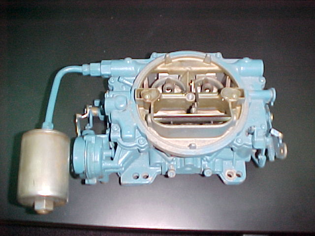
The carburetor
The carburetor is an aftermarket Edelbrock. The original Carburetor is a Carter AFB. Carter AFBs are still (occasionally) available through my Carburetor Supplier and are excellent carbs. This carburetor was apparently operating properly when the engine began to fail and may be re-used.
The transmission:
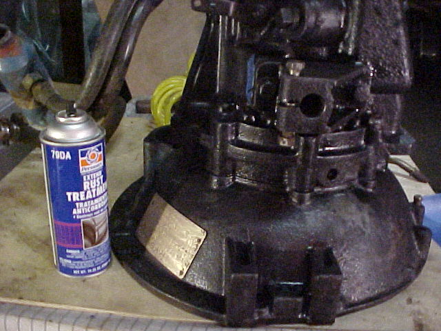
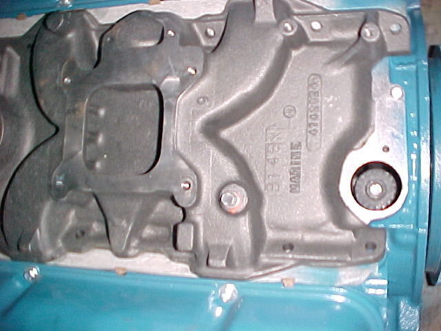
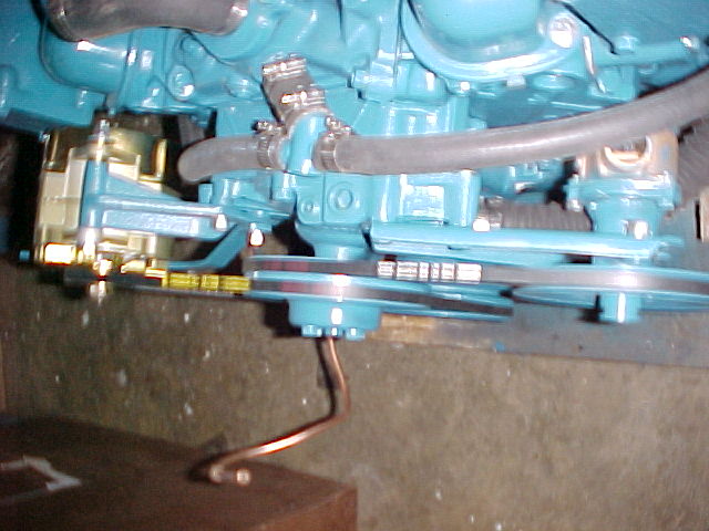
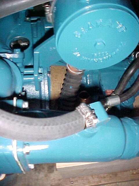
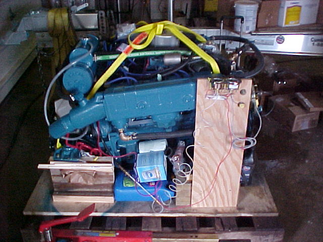
The transmission is a Velvet Drive (brand) and is probably original to the boat. A quick "disaster" check of the transmission fluid shows that is was low... and a bit dirty... but smelled like fresh fluid as opposed to having the ole "burnt toast" smell. The burnt toast smell, if present, would have indicated slipping friction material. The "jury is still out" until we do a drain and re-fill of the fluid, however there was no "disaster" found. It seems we will be able to re-use the transmission without rebuild if the customer desires. The location of the transmission oil dipstick is obscured by the engine oil dipstick in this picture. The dipstick is attached underneath what appears to be a pipe plug with a square head. Note the black arrow - the dipstick is just above the arrow.
/\
Sunday - November 30th Update
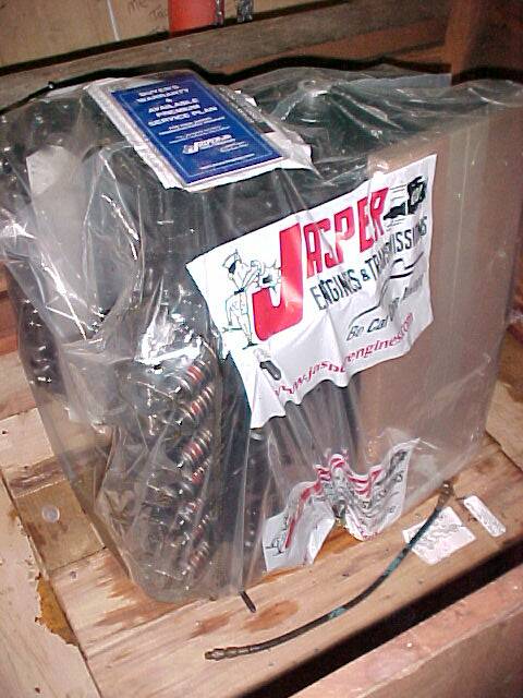
The Engine and transmission assembly is off to Jasper Indiana for remanufacture. The Jasper Engines truck will pick the engine up in Lexington KY on Monday December 1 and after picking up other engines of various manufacturers in other cities it will complete it's route in Jasper Indiana sometime Monday night.
The starter and alternator were also sent and they will be rebuilt by other parties and sent to Jasper for installation on the engine.
The new exhaust manifolds will be ordered on Monday December 1st and will also be sent to Jasper Indiana for assembly on the engine.
As transportation to Jasper Indiana will take until Monday night, the engine won't be evaluated by Jasper until Tuesday morning at the earliest. Our only concern right now is that since the engine has already been bored .030" over and engine wear has been up to .0095" there may be too little engine block there to bore successfully to .040" over the original diameter. If the existing block can't be used it may cause a delay in the process... a delay we really don't want. We will hope for the best until Tuesday when we find out if we have to find a new (to us) block.
Info On engine
Chrysler 210 H.P.
LM 318 BRW10
Serial# 121394
Year approximately 1974
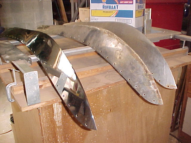
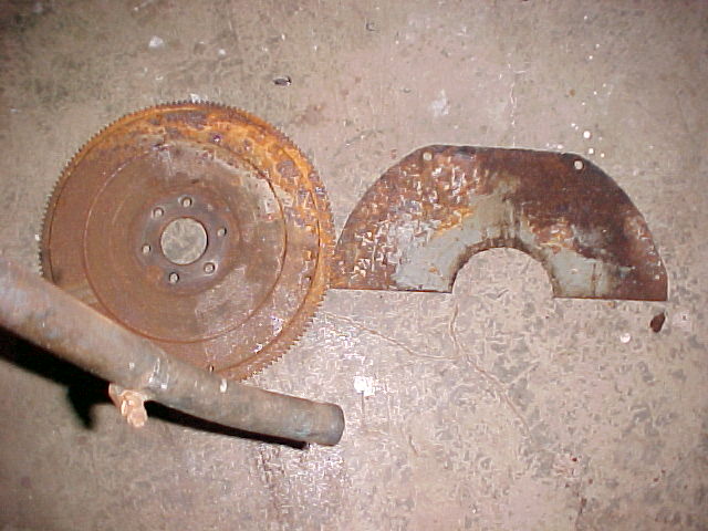
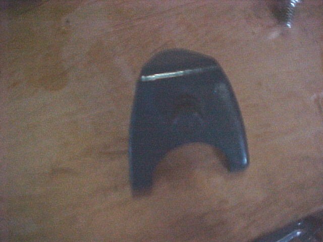
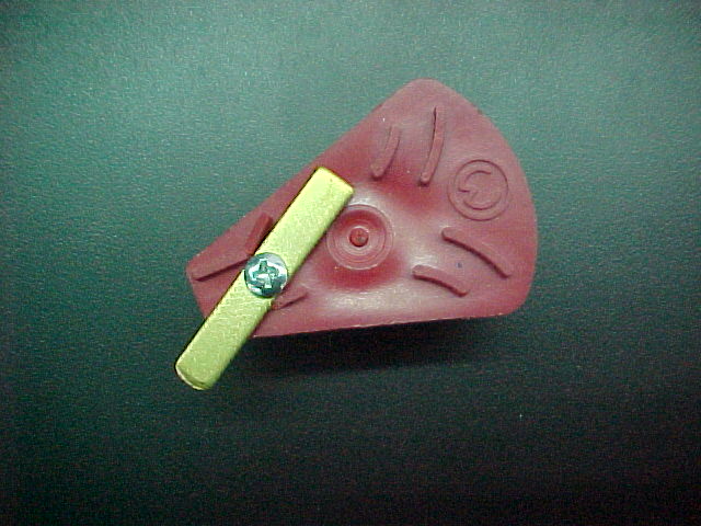
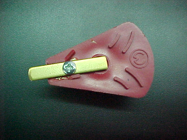
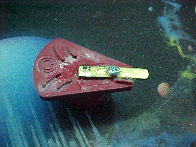
Along with engine work, a new cutwater was fabricated. 316 Stainless steel was selected as the raw material as it has superior salt water resistance. The original cutwater (in center) was made from 304 stainless steel and has corroded through in places. The cutwater to the right is that of a sister to the boat that gets the new cutwater. An older sister in fact - a 1946 22' Sportsman
Saturday - December 27th Update
The Engine is back from Jasper Indiana, and we have been working to complete the assembly of the engine. When it was determined that Clearing Customs was going to "blow our schedule" we took a couple of days off for Christmas.
As we began to assemble our "jigsaw puzzle" we found there to be additional issues that needed to be addressed. You'll see pictures of these issues but to summarize
Missing Distributor
Cracked hydraulic hose on transmission
Missing stud for attaching carburetor
Damaged dipstick tube
Potential Engine mount to engine stringer problem (wooden engine stringers on boat in Belize)
Rust
on transmission housing
on transmission to flywheel coupling plate
on flywheel
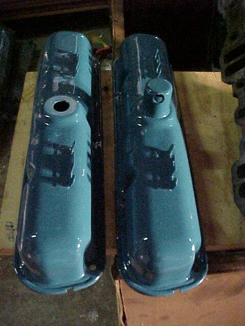
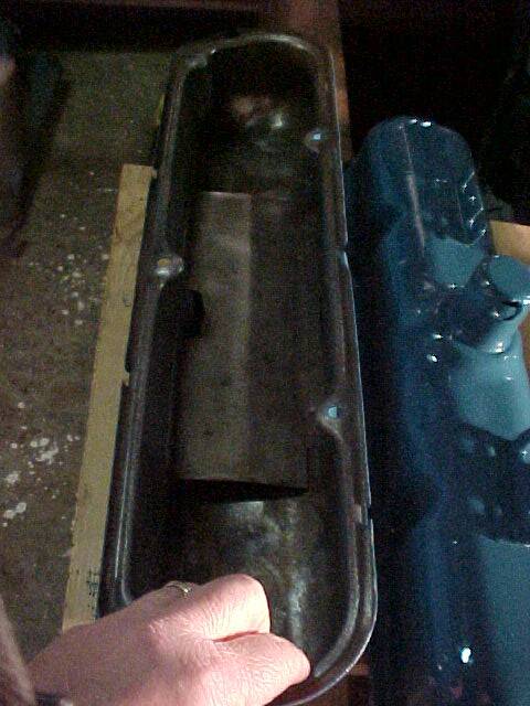
in and on valve covers
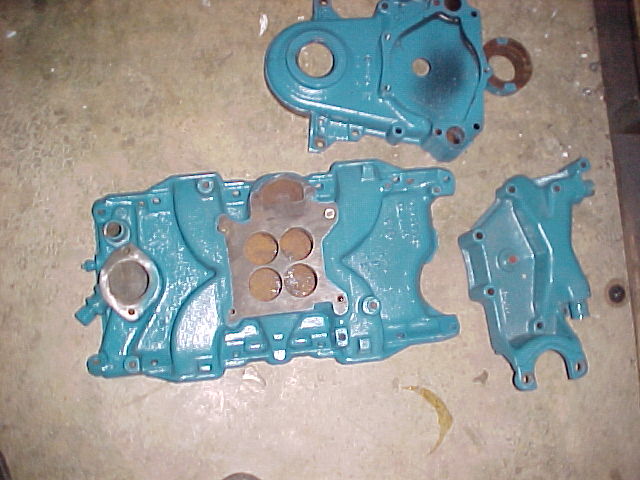
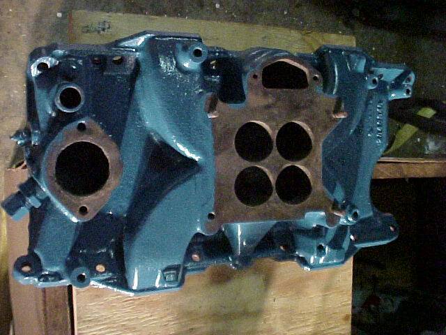
in and on intake manifold
preventing adjustable engine mounts from adjusting
The pictures below show the problems and the corrections made
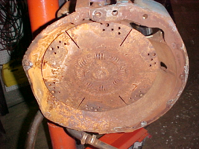
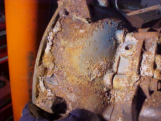
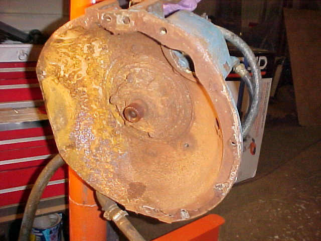
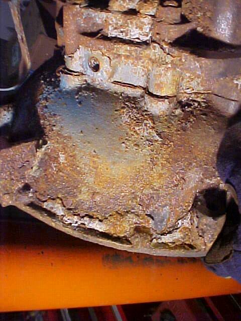
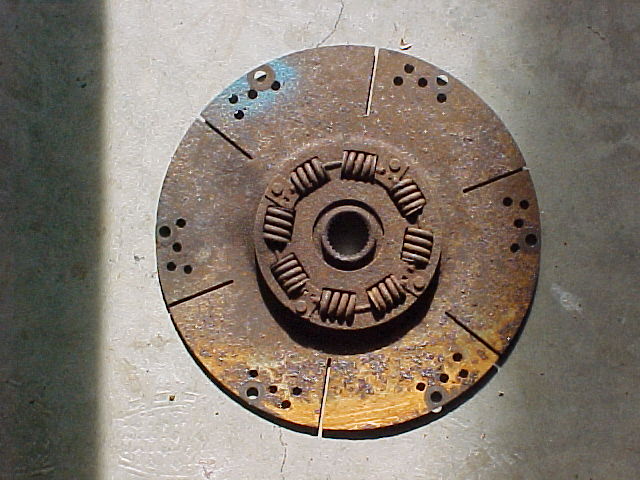
The rust on the transmission didn't look so bad as viewed from the top ( top left picture) However, it was so bad on the coupling plate that bolts to the flywheel that a good connection could not be made without cleaning it off. The plate (in top center picture) slides over a splined shaft on the transmission - but was rusted to the shaft. A little oil and time was required to be able to remove the plate from the transmission. The plate has the springs (arrow #1). We recommend that the plate not be re-used as the springs and the mechanisms that retain the springs are rusted thereby making the assembly prone to failure. The top right picture shows the transmission bell housing with the coupling plate removed - More rust! At arrow #2 in the bottom right picture the rust is so thick that a layer of rust had to be chipped off with a welding / chipping hammer before the wire brush could be used to complete the rust removal.
/\
/\
1
2
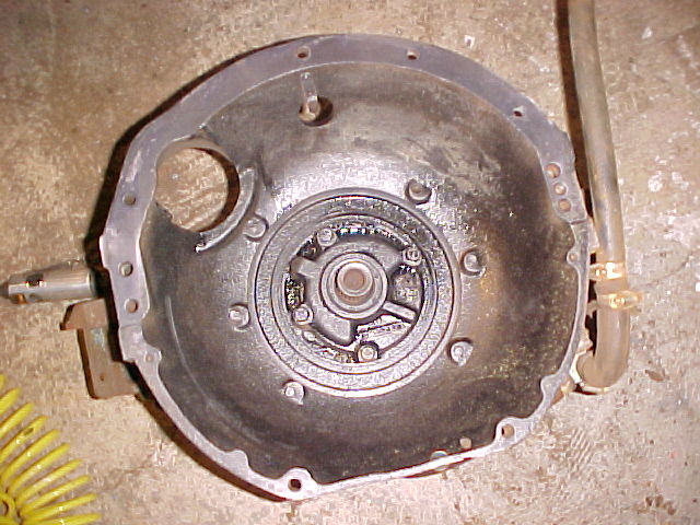
Pictured above is the inside of the transmission bell housing after the rusted coupling plate has been removed. The right hand picture shows the same assembly after the rust was cleaned off with wire brushes mounted in die grinders. After removal of the rust the metal surfaces were treated with Permatex, Extend, rust transformer. This spray on coating actually reacts with the metal surface and any remaining rust to ensure maximum protection from corrosion.
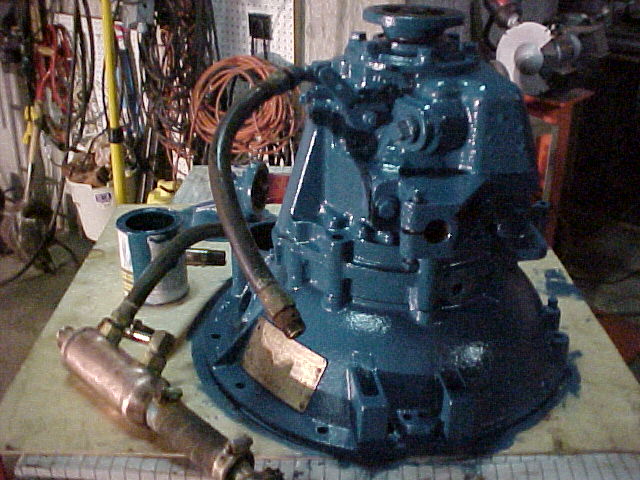
Pictured above is the outside of the transmission surface before cleaning, after treatment with extend and after painting Chris Craft Blue.
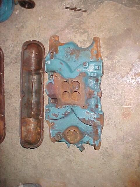
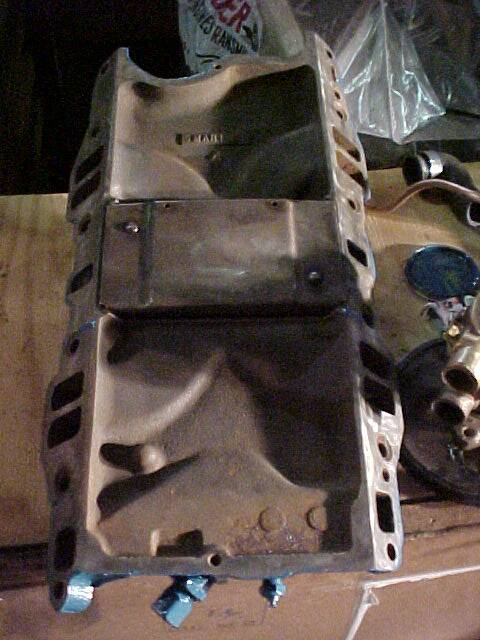
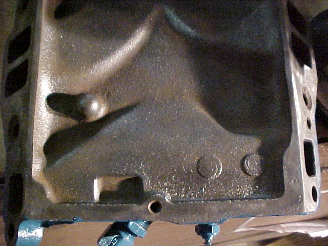
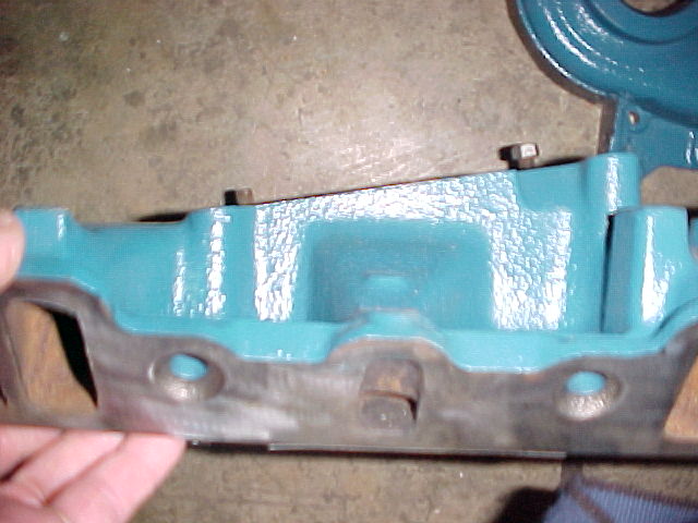
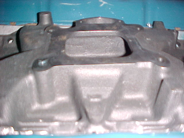
Pictured in top row above is the rust INSIDE the valve covers (top of top left picture) and the rust under the intake manifold (top center picture0 and the rust removed from underside of intake manifold (Top right hand picture) . Both the inside of the valve covers and the inside of the intake manifold will have engine oil splashed on them during operation of the engine. We don't want the rust to release itself into and contaminating the oil circulation system as a result of this splashing / washing.
After pictures are the bottom row.
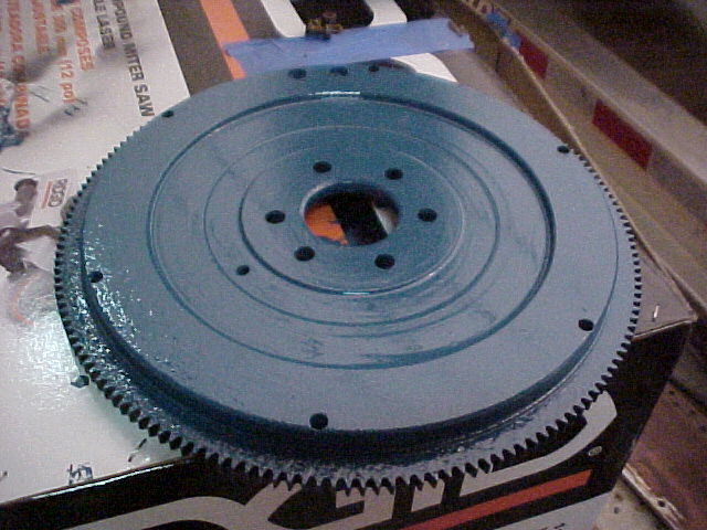
Engine flywheel - before and after.
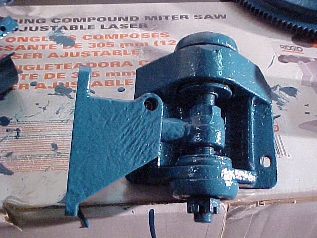
The engine mounts were rusted to the point they could not be used to adjust the engine as required to align the engine to the propeller shaft. It took some doing - even after soaking the mounts in mineral spirits for a day while we cleaned and painted all the other parts - but we managed to free up all the bolts, nuts and clamp fit parts so that when the engine is installed it can be properly aligned!
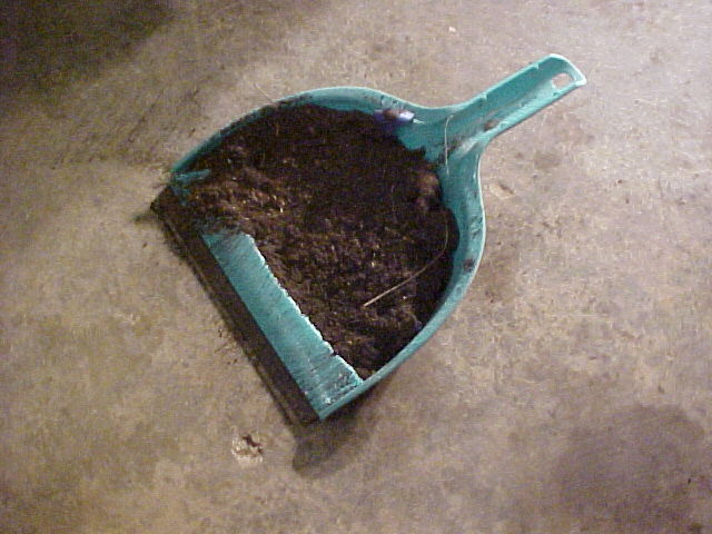
The debris... mostly rust.... that was removed from the parts filled the air in the shop, our noses, and also an entire dust pan!
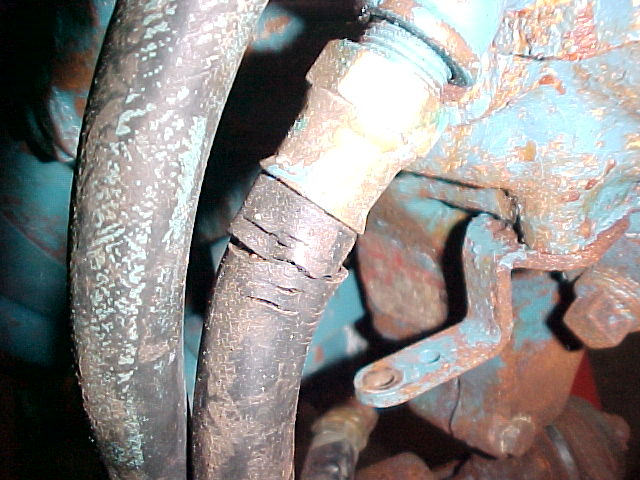
We found a cracked hydraulic hose on the transmission... This hose, and the 2nd hose that circulates oil from the transmission through the transmission oil cooler will be replaced.
/\
Above the white arrow is a missing carburetor mounting stud.... this could seriously hamper performance as air could leak in here past the carburetor and cause an incorrect air to fuel ratio!
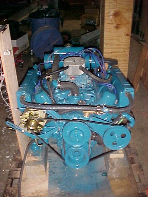
Pictured above is the remanufactured Long block assembly. The Long block consists of block, pistons, heads, crankshaft, cam shaft, oil pump, oil pan, and all the timing gears, chains and enclosures. We are NOW ready to begin bolting on
valve covers
intake manifold
carburetor
starter
alternator
exhaust manifolds
engine mounts
flywheel
transmission
water Pump
Then run the engine to verify performance of carburetor, starter, alternator and cooling system, and transmission.
Take care of any issues that may arise
Then crate the engine for transport to Belize!
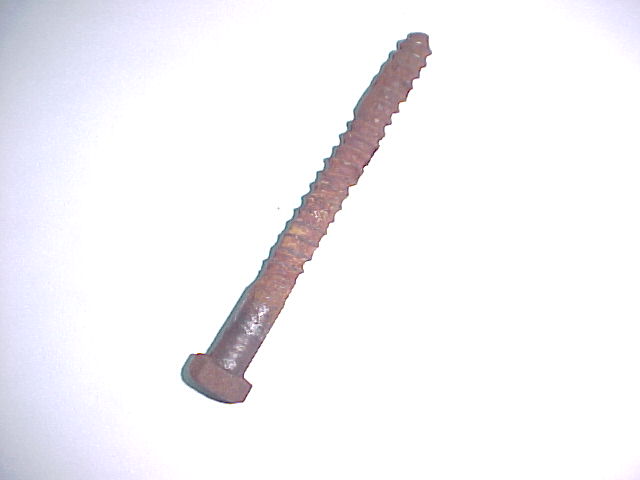
Note the picture above, This is an engine mounting bolt that came in with the engine. Note the rust filling the spaces between the threads of the lag bolt. We have seen this before, there will be rot in the engine stringer around the hole where the bolt is supposed to grip the wood. The bolt will not grip the wood, but spin freely and not securely hold the engine in place. We will bring plugs and drill bits to enlarge the bolt holes in the stringers and plug them with new wood. Then re-drill the holes and supply and use new Stainless Steel mounting bolts so this problem does not repeat itself!
Friday - January 2nd Update
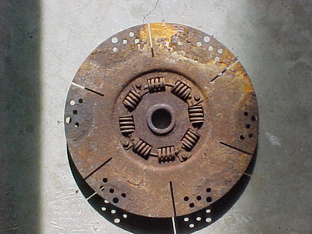
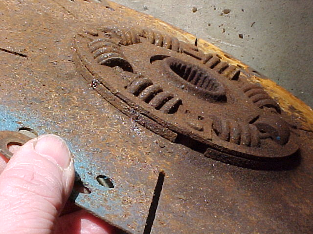
Just a little more detail on the rusted dampening plate that couples the transmission and the Engine together. We are in the process of finding a new one as the condition of this one has been compromised by rust. The springs that would dampen any shock loading say due to hitting an obstruction are being held in by some very thin sheet metal "clips" that are themselves severely corroded and held in place with some corroded rivets. The rust on the floor in the lower right hand picture came off the dampener / coupler plate with 6 or 7 sharp raps of the plate against the floor.
/\
/\
/\
Overall, what has occurred since the last update is:
Some painting and cleaning, purchase of new hydraulic hoses for the transmission, and water hoses for the cooling circuit.
Also, placed on order are a thermostat for the cooling system, spark plugs, plug wires and a set of the proper bolts to mount the intake manifold, replacing the bolts that were missing in the shipment from Belize.
A new distributor to replace the one apparently still in Belize has been priced and we are hoping to get an opportunity to assess the condition of the original one due to the cost of a new one.
Lastly we discovered a new issue to resolve... why is there a "glob" of silicone caulk plugging a hole in a water / cooling system housing, and what needs to be done about it?
Finding and pricing these parts has been hectic at best in this holiday season with many suppliers taking time off from Christmas Eve until the Monday after New Years!
And here it is - the mystery hole - with precious cooling water being held in the engine by a dollop of red RTV Silicone sealant?!?!?!
Our 247 page service manual does not indicate what this fitting should have connected to it, nor does any part that came in with the engine as it arrived from Belize. So we have ordered a $37 parts manual which should indicate what this was to be used for. A bypass hose possibly? Rather than speculate we will use our new $37.00 of knowledge to determine its use. As of press time today the manual has not arrived, but it is expected today.
/\
Thursday - February 12th Update
Here are most of the new engine parts. The new parts were left unpainted for now so they can easily be identified. This photo can be referred to in the future for parts identification / discussions with the on site maintenance personnel in Belize.
The new intake manifold is on top -1
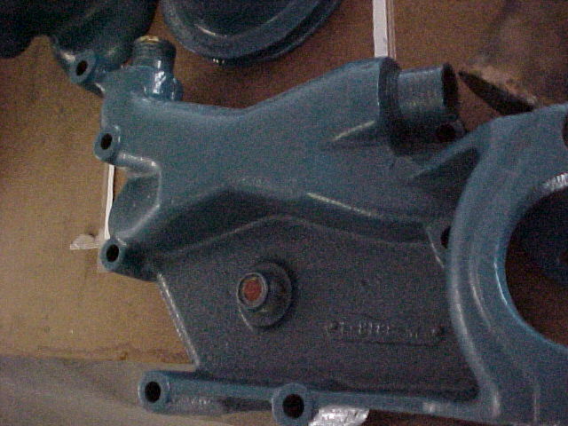
The new timing chain case cover is right below it - it is gray and has a black water pump mounted in front of it. - 2,
The new circulating water pump is black and has a new black pulley mounted to it - 3 This pump will circulate a water and antifreeze mix through the block, exhaust manifolds, and heat exchanger. This is a pump the engine didn't have before FWC.
The new raw water pump mount is #4
Still to mount at #5 Crankshaft end - is one new pulley, a new spacer and the original pulley. One of these pulleys drives the alternator (not yet mounted - mount ordered but not yet received.) and the other pulley drives the raw water pump. In both the case of the raw water pump and the alternator the belts will go around and also drive the circulating water pump.
1
2
3
4
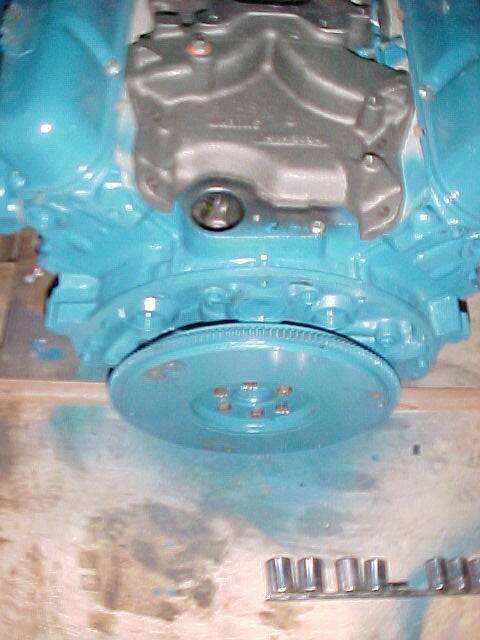
This is the rear of the engine with the flywheel attached. To this we will attach a new damper plate, which will couple the transmission to the engine. Then the new starter will be mounted on the transmission housing. The gear on the starter motor will engage the gear teeth visible on the flywheel. The gray object is just another view of the intake manifold.
The hole in the block just below the intake manifold is where the new oil pump drive shaft was installed, and where the distributor gets installed.
Sorry for the picture quality, but this is the distributor hold down clamp that we purchased to replace the missing one. It was "harvested" from a used engine.
Pictured above is the new intake manifold - not yet mounted. Through the hole in the block the oil pump shaft that was lost and replaced by the engine block rebuild is visible. There is a slot in the top of the shaft ( the bright spot in the center of the gear) that the distributor fits into to make a positive coupling for rotation. See #1
At #2 is the location for the choke control should we decide to replace the carburetor with the original type - Carter AFB.
1
2
Pictured above are some of the old parts.
Pulley spacer ( the ring in the upper right) The original one is too thick for the new application.
Timing Chain case cover - note the hole in the center of the chamber by the #1 This was for the tachometer mechanical drive shaft to come through. The tachometer drive shaft would have been coupled to the cam shaft.
The lower right object was a water passage and water pump mount. The old water pump mount was at #2 The new circulating water pump mounts on the new timing chain case cover in the same relative location where this part used to mount on the old timing chain case cover. The hole at #3 is where the tachometer cable coupled to the engine. This was filled with silicone caulk!
The lower left object is the old intake manifold. Note numbers 4 and 5. #4 is a fitting for the bulb on the end of a capillary tube type temperature gauge. I suspect the gauge in the boat is a capillary tube type as this fitting is not plugged. In the new manifold this opening on the intake manifold has a water outlet fitting. We will have to determine how to install this fitting in our system. Stay tuned on that. #5 is a temperature "sender" for an electronic gauge. We could use the option of an authentic looking gauge with an electronic movement like we are doing on the tachometer. However, this signs us up for another expenditure. So before we decide to do this we need to see if we can install the capillary tube type gauge fitting in the system first.
1
2
3
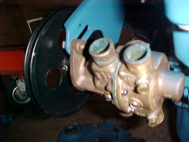
Pictured above is the original dual pocket water pump we are / were trying to re-use. It is capable of delivering more water (Gallons per minute or GPM ) than a single pocket. Which is a good thing. We talked with Sherwood's experts and got the OK to use this pump on this application. However, while the pump is capable... it does not fit in the space we have. The bracket could be modified, however the time and effort to do so would likely be as much or more as just
putting the proper pump in place.
Note in picture to right we are out to the end of the drive belt adjustment slots and (ref left picture) we have only about 1/4" of space between the block and the pump.
1
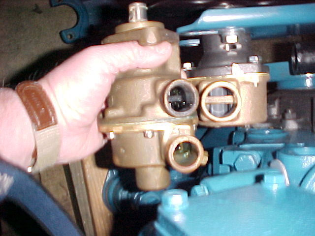
Pictured to the left is the proper single pocket pump - ordered by mistake two 2 weeks ago and ALMOST sent back. I am holding the dual pocket pump next to it. Now I see why they changed the pump to a smaller pump!
I decided to hold on to the single pocket pump ordered by mistake until the engine was together and it was a good thing I did!
How this occurred
My supplier had quoted the distributor hold down clamp and the pump at the same time. He called back to see if I wanted the "hold down clamp and stuff" and I said "yes" I didn't find out the stuff was the water pump that I didn't think I needed until I opened the box! SOMETIMES luck takes care of us.
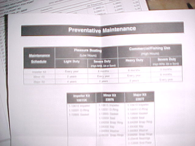
Pictured above is the preventive maintenance schedule for the pump. It is hard to read, but suggests changing the impeller every year if the boat is used for pleasure and is light duty (not many abrasive materials suspended in the water it is pumping).
4
5
There is one more issue that has arisen that has to be resolved for FWC. The new intake manifold is the flat style - no angle for the carburetor to sit on. A wedge will have to be purchased to put the carburetor on the proper angle for good performance. List price on an 8 degree inclined wedge is $45. We will be double checking the incline with a protractor before placing an order.
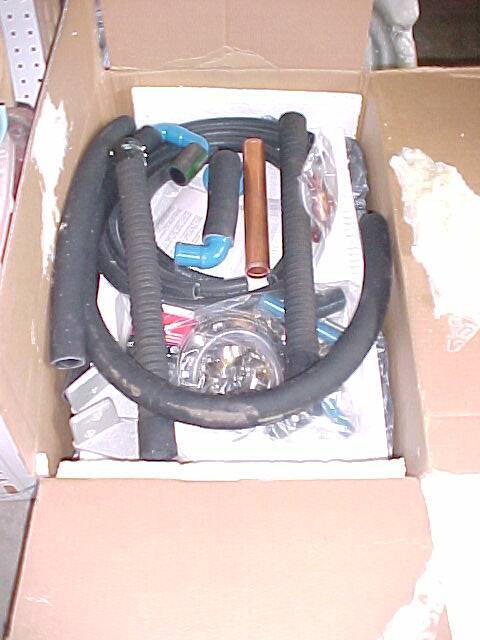
The fresh water cooling kit has arrived!
We are awaiting an alternator bracket.
Tuesday - February 17th Update
Left
It seems with every new part that goes on a new issue arises.
The distributor didn't fit when when installed on Saturday eve. However double checks of the part number confirm the right part number. A call on Monday morning to the supplier revealed there is a spacer that is used on the Right Hand rotation engines that is not used on the Left hand. A spacer was shipped from the warehouse in Michigan on Monday afternoon and should arrive by Wednesday afternoon.
There is a really tight fit between the new starter and the neutral start switch. We pulled the old starter parts out of a box and checked dimensions... sure nuff the new starter matches the old starter dimensions! We don't get rid of anything until the project is complete just so we can resolve any questions that arise.
Also note the heat transmission heat exchanger - above arrow /\. It has to be changed to match up with the new FWC system. See other notes later on in update.
Below
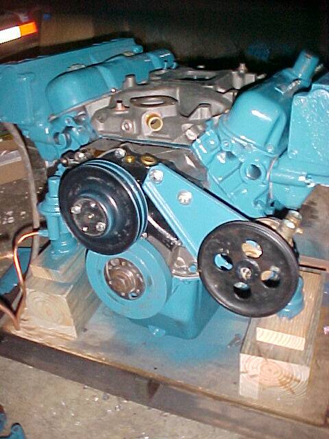
The new alternator and water pump are installed. Even the new brackets holding these items had to be modified to fit the engine. So much for mass production techniques! Before modification the pulleys did not align properly which would have led to v-belts being slung off and premature belt and bearing wear. Note the alignment in photo below right. The modification on the water pump mount (left mount) are shims that ware welded in place on the mount so they can not be accidentally lost in the event of other mechanics working on this engine in Belize. Several areas on the Alternator mount had to be adjusted by grinding some of the cast material away. Also note new fasteners have been used to assemble the engine as the old ones were rusty and most of the protective plating was gone. It was less expensive and better to replace fasteners instead of cleaning them on a wire brush.
The FWC system installation has begun. The heat exchanger and expansion tank are mounted on the rear of the engine. New end plates (not replaced with the manifolds) are on the way that have water outlet holes cast in place at points 1 and 2
1
2
3
4
The inlet to the heat FWC heat exchanger and the outlet from the transmission cooler are not the same diameter. The transmission cooler ( just a smaller heat exchanger dedicated to the transmission) has a 1" diameter inlet and outlet and the new FWC heat exchanger has an inlet and outlet of 1-1/4". A new transmission cooler has been ordered that has 1-1/4" inlets and outlets so there is no restriction of critical cooling water flow.
The carburetor looks a little tired... it was previously painted - sort of.... and it has a little corrosion on the throttle plates. We will be testing this carburetor on the engine hopefully later this week. If it does not perform well a new carburetor has been located in Atlanta GA.
/\
Mounting blocks have been added to the assembly for running the engine prior to shipment and to protect the engine during shipment. New stainless steel lag bolts have been purchased to attach the engine to the engine stringers on the boat in Belize.
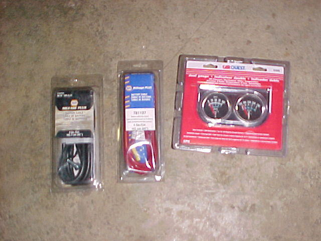
New battery cables have been purchased since we don't know the condition of those currently on the boat. Also, in order to run the engine in the shop these are needed. An inexpensive set of mechanical gauges for oil pressure and temperature have been purchased so we can monitor the engine during testing of all the systems. We will also have to purchase an ignition coil and starter solenoid as these did not make it up here from Belize with the engine.
Wednesday - February 25th Update
The inexpensive set of mechanical gauges for oil pressure and temperature purchased so we can monitor the engine during testing of all the systems has been installed on the plywood to the left of the left hand picture. The FWC system is completely installed including the new transmission oil cooler ( see gray heat exchanger in right hand picture.
The new start solenoid, ignition coil, carburetor gasket, and ballast resistor arrived yesterday and have been installed. We determined the supplier sent us the wrong start solenoid and the proper one is on the way at no additional charge. It should be here tomorrow. We will be able to adapt the one we have on a temporary basis and not have to wait on the proper part to run the engine.
The engine has been filled with 7 quarts of oil, The new distributor is installed and new spark plugs and wires. As soon as the oil dipstick tube gets here (today) we will be starting the engine. We are waiting for the oil dipstick tube, While we are waiting for the dipstick tube we will change the transmission fluid the existing oil is a bit dark - indicating contamination and possibly reduced lubricity.
The rotor (located under a new distributor cap on a new distributor was faulty. In the picture to the left the rotor is damaged, the picture on the right shows how this part should look. This resulted in the engine not running properly. This is a Mallory part and we have been unsuccesful in finding it locally, and even within a 35 mile radius. Actually except for the delay, I'm glad this happened as it illustrates the need to carry some spares.
Recommended Spares
This list is not necessarily all inclusive...it is a list of the minimum spares we should have available in Belize.
Oil Filter
Oil (7 quarts capacity with new filter element - 6 quarts when not changing filter)
Distributor Cap
Rotor
Points
Condenser
Starter Solenoid
Thermostat
Thermostat gasket
Touch up Paint
Water Pump Impeller
2 quarts DEXTRON III transmission fluid (3 if oil cooler drained)
XL 7450 - Alternator Belt
XL 7460 - Water Pump Belt
Ignition Coil
Fuel Pump
Engine Service Manual (HIGHLY ILLUSTRATED! - for communications with Belize personnel )
Engine Parts Manual (HIGHLY ILLUSTRATED! - for communications with Belize personnel )
See and hear this engine run!!!!
We just dispise delays here at Woodies. Since we couldn't find the replacement part locally we ordered the parts, and then too matters into our own hands. We ground off the tip of the metal contact a little at a time until it no longer caught on the inside of the distributor cap. Then we glued the contact in place with what I like to call 120 Mile per hour glue. We were able to run the engine and complete our tests before the replacement parts arrived maintaining our Monday ship date! Do you remember the show McGyver!?!?!?!? The replacement rotor and distrubutor cap are now in place and the engine re-tested!
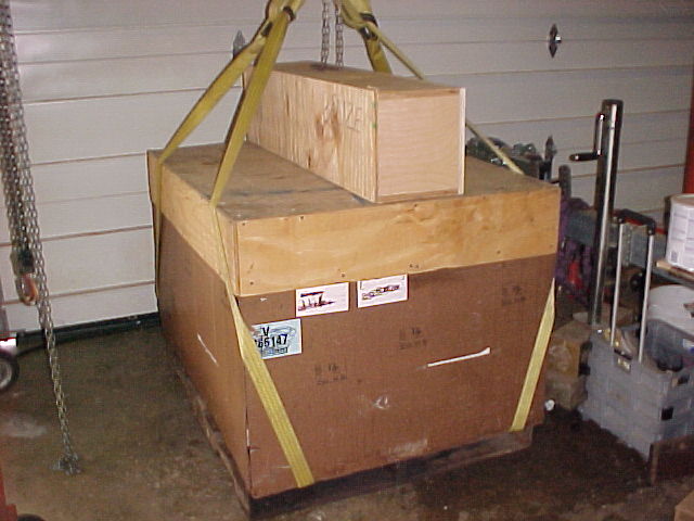
The crate is packed with the engine and the spare parts and ready for shipment! We drained the Fresh water cooling system of sea water. The anti-freeze protected fresh water remains in the engine. We even included bolts lockwashers and nuts for the transmission to prop shaft coupling as they may be in someones pocket, inside a clothes washer or on someones dresser in Belize. We don't want to have to find them once there! We also included the test gauges in the shipment. They may come in handy in the future if we suspect an original gauge is not working properly. We can just hook up either this temperature gauge or the oil pressure gauge and verify the condition of the original gauges.
Note the 4 yellow straps. Each strap is rated to lift 1900 pounds in the choker configuration. That is nearly twice the weight of the engine. We don't want to take a chance on dropping the engine while it is suspended over the boat. We aren't going to use the bolt through a chain method!
Spares attached to the engine include spare:
Sea water pump impeller
Anti freeze and oil
Transmission fluid
Start Solenoid
Points and condenser
Oil Filter
Exhaust riser gaskets
Engine to boat mounting bolts and dowels for bolt hole repair
Water fitting adapters with extra intake hose.
Oh, the box on top of the engine crate... the Cutwater!