270-866-2628 Paul@woodiesrestorations.com
Update September 11, 2008
Update September 12, 2008
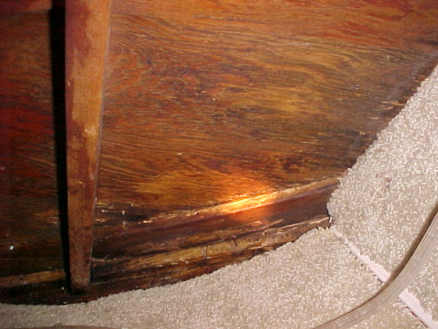
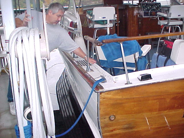
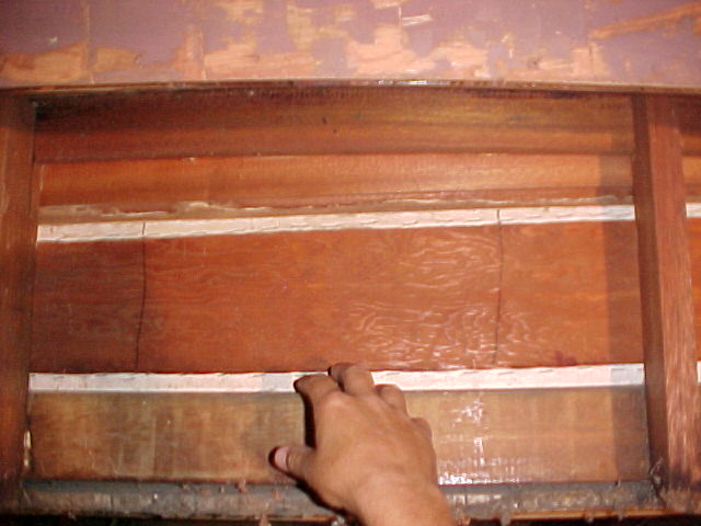
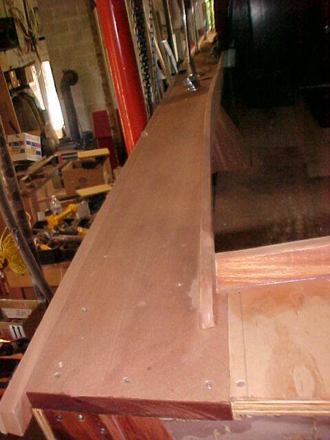
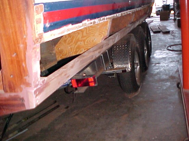
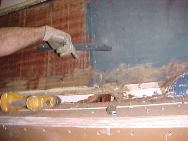
The replacement transom "shelf" has been installed and the supports to the rear deck have been sister framed as well. All rot has been cut out, and in addition, everything has been treated with smiths CPES to prevent any rot spores already present from attacking the new wood for many years to come. There was some mold (first stages of rot) on the back of lower decorative trim as seen from the inside of the cockpit. The mold was sanded off and the lower part of the board treated with Smiths CPES as well. (note the band of darker color at the bottom of the board.
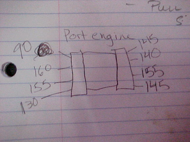
A compression test was completed on the port engine - after a new battery was installed, AND new cables. The old cables were badly corroded at the terminals and after cutting the old cables back two times, in hopes of applying new terminal ends, but still finding corrosion we determined the best fix to be to replace the cables.... the old ones would also have been too short once we cut them again!
We also did a load check on the existing deep cycle batteries and found one of the existing batteries to be bad ( 10 volts before load dipping to 0 volts under load) This is a battery we charged for 24 hours! The second deep cycle battery on that side was very good ( not excellent ) 13 volts before load, and dipping to 11 under load. Very similar to a brand new deep cycle we have for our grand daughters 8 foot kiddie runabout.
So work completed here
- New Engine battery
- New battery cables
- Compression test
- Check existing batteryies
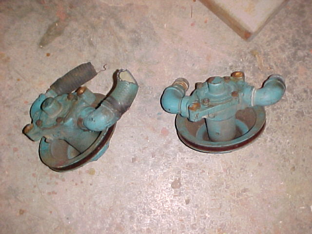
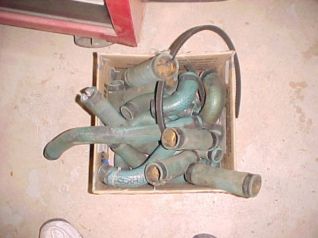
The water pumps were removed to prepare for replacement of the impellers. We found one of the inlet hoses (from the water inlet under the boat) "fell apart in our hands" . The other was in fair shape but will be replaced as a precautionary measure. An outlet hose from the other water pump also fell apart.

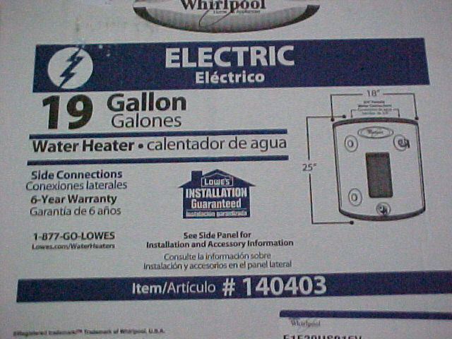
The 6 gallon water heater was removed and thus far the 19 gallon heater was selected and purchased in the owners behalf. The heating element is 1500 watts, 120 volts. The recovery rate will be about 35 degrees per hour - so 70 degree water will be 105 at the end of an hour. In less than 2 hours the entire 19 gallons of water will be at the max temp of 135 degrees. So the recovery time is a little slower as the heating element is the same as in the 6 gallon heater, but since there is over 3 times as much water in this heater recovery time should never be an issue!
We found an on / off switch located on the old water heater that will be reused.
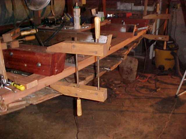
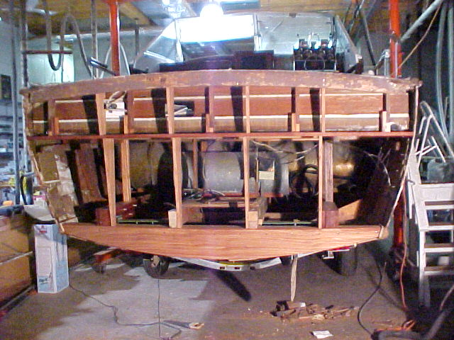
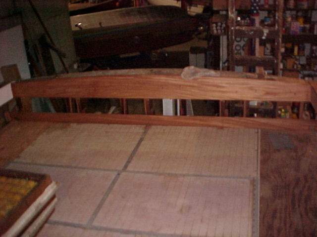
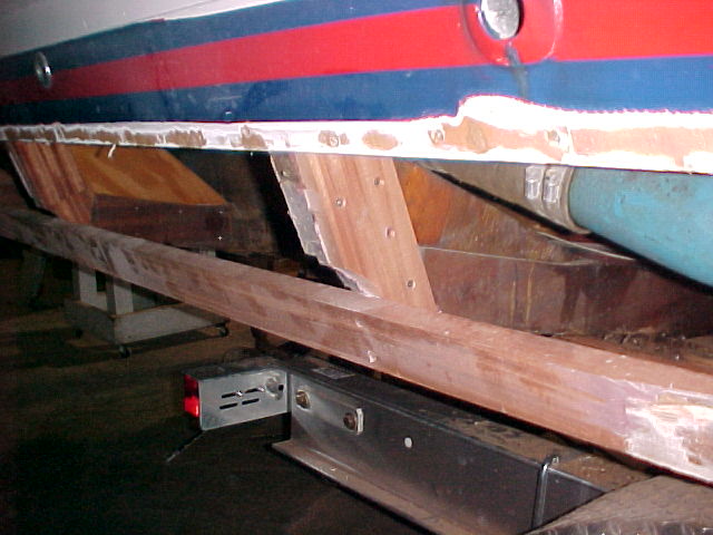
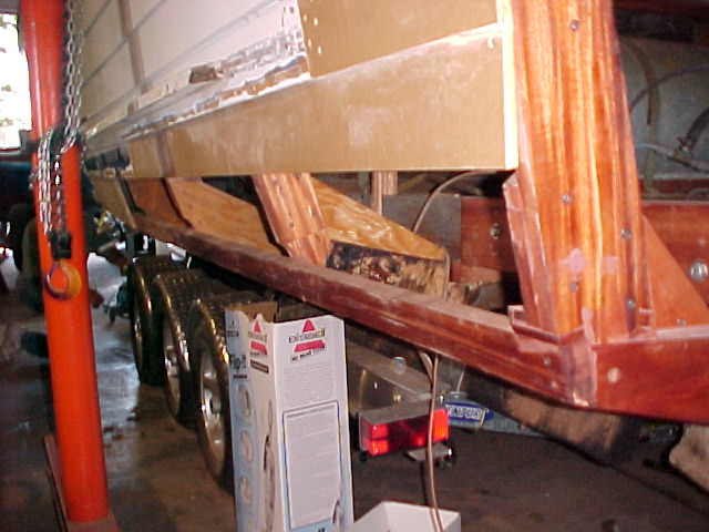
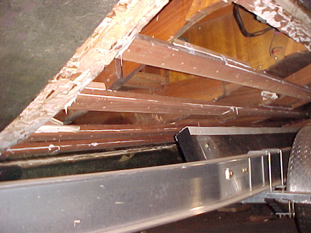
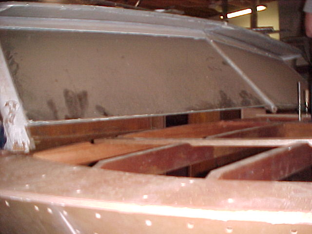
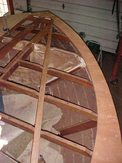
Shown are the sistered longitudinal stringers and the "STRONGBACK". Since everything was so damaged due to rot we determined we needed to build a strongback to bend the transom bow to. This would be the only way to get the proper shape to the bow since the bottom had to be cut away to remove the bow, but mainly due to the poor condition of the ends of the longitudinal "battens". This new strongback and bow assembly will provide a "foundation" to build the new bottom to.
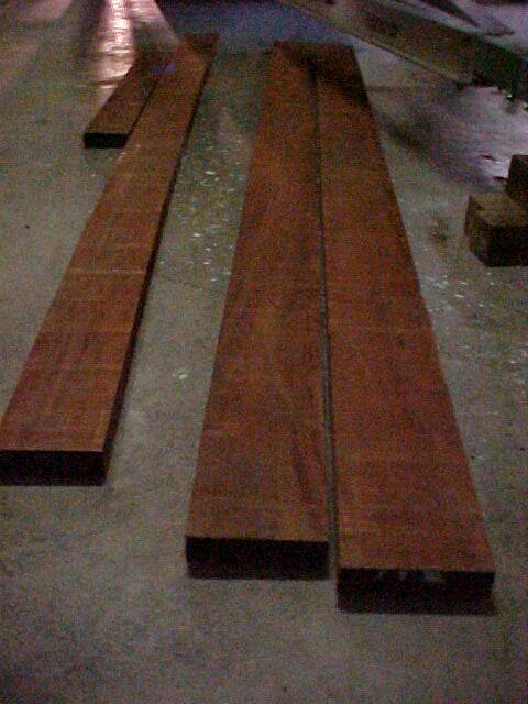
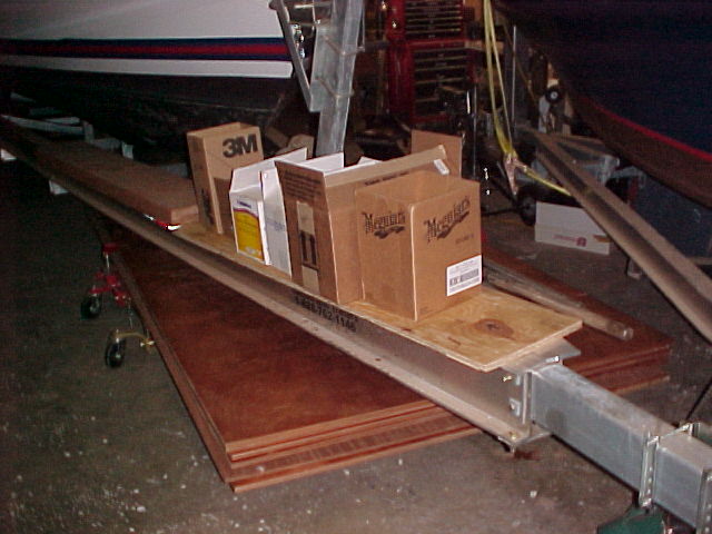
This is part of the new mahogany purchased on Tuesday afternoon. The planks to the right will be resawn to become the transom planks should we not be able to find the 12' plywood we seek. Either way. The transom will be left open as until after the stern section of the bottom is replaced in order to provide easy access to the rudder and rudder packing gland assemblies.
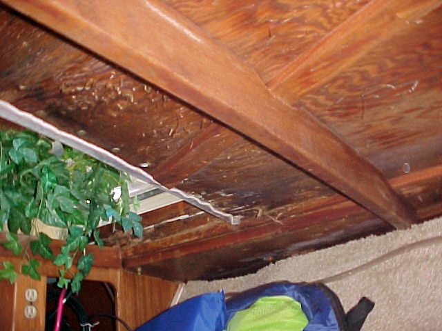
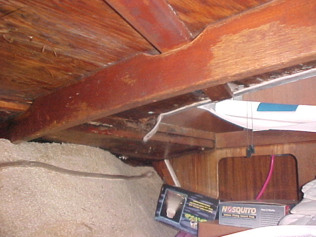
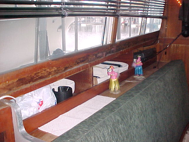
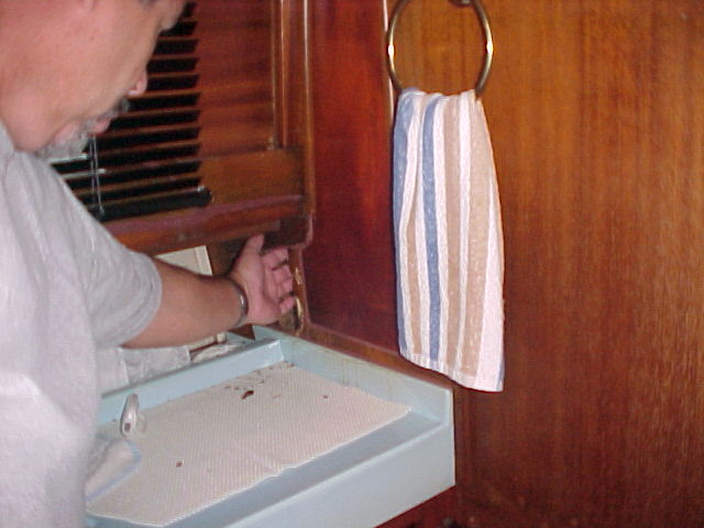
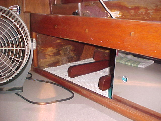
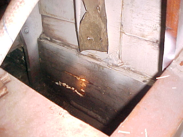
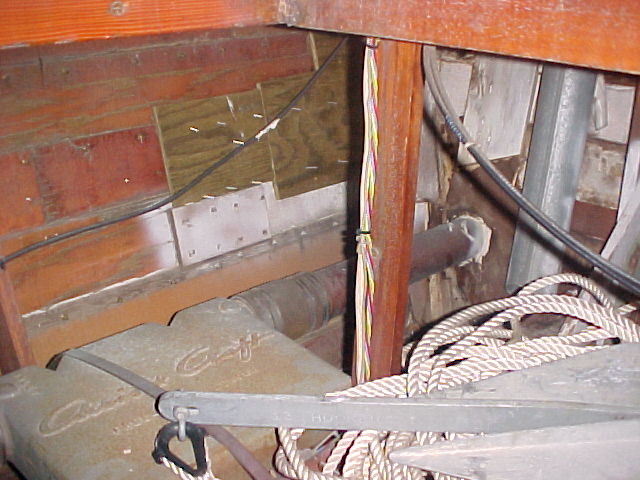
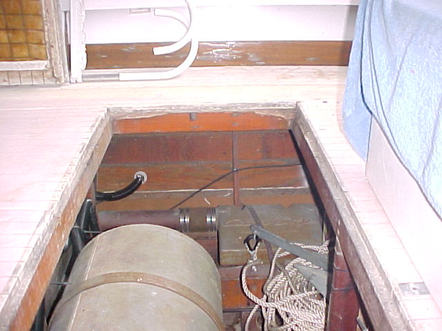
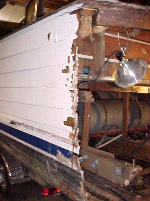
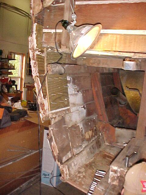
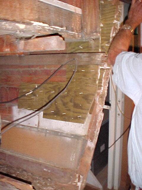
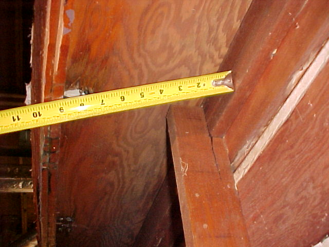
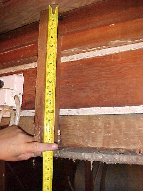
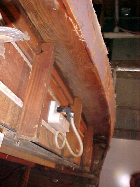
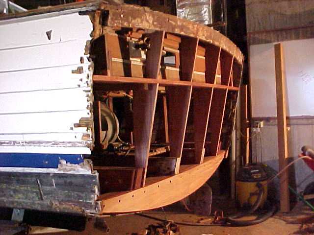
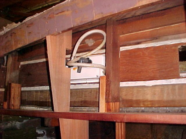
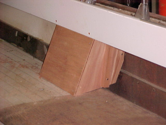
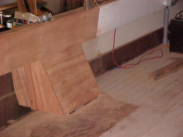
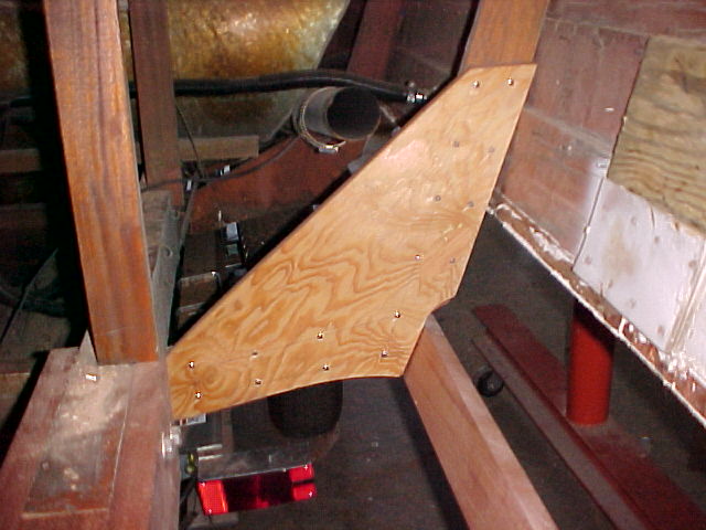
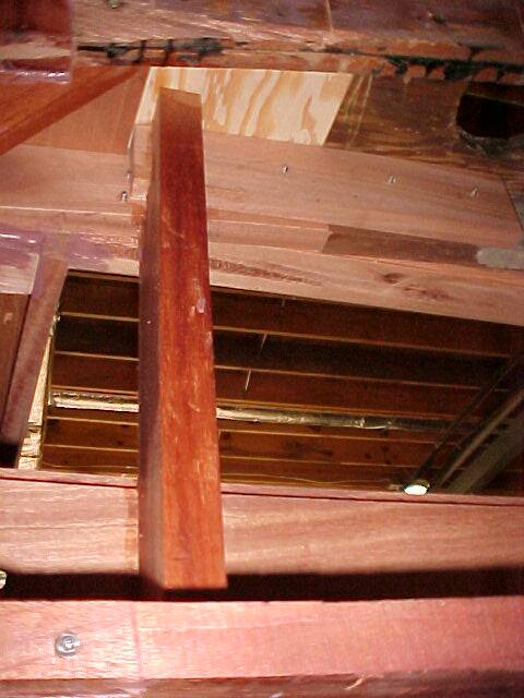
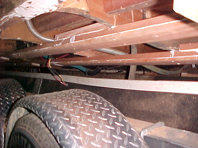
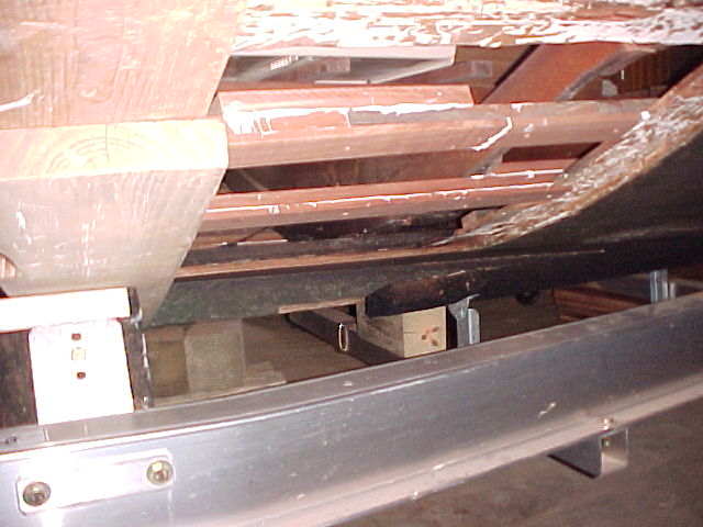
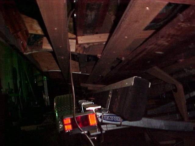
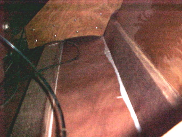
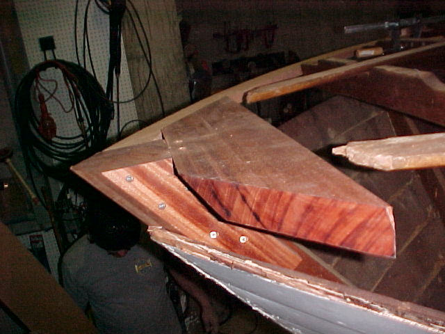
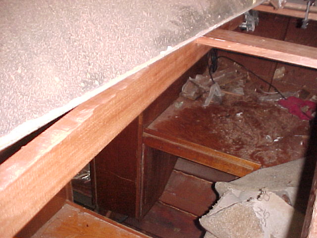
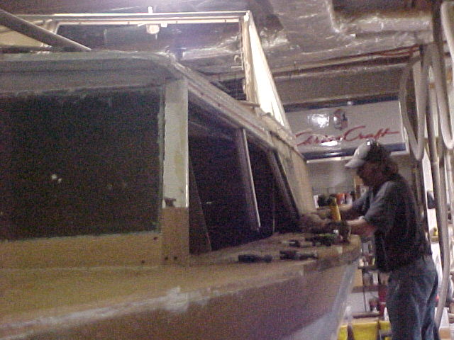
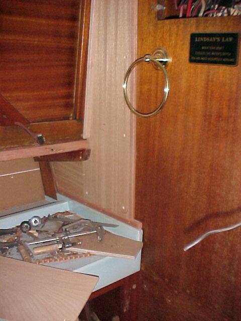
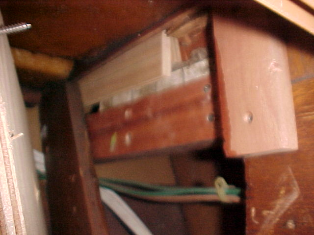
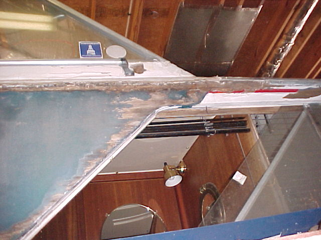
The 4 pictures above illustrate the space available for some storage pockets to be built in to the transom as part of this process. The shower will be moved to the port side and the opening enlarged to create a pocket. In the frame bay to the starboard side the process will be repeated.
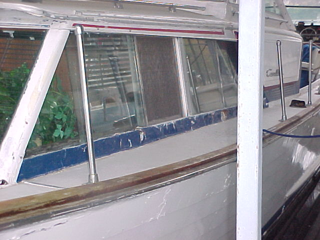
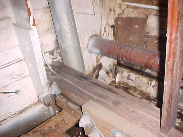
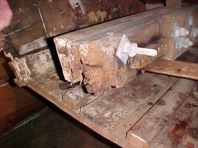
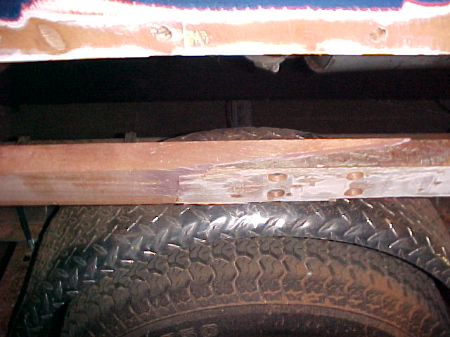
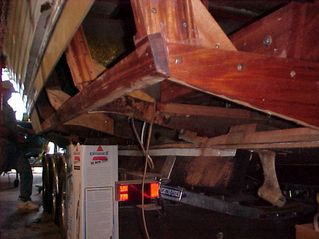
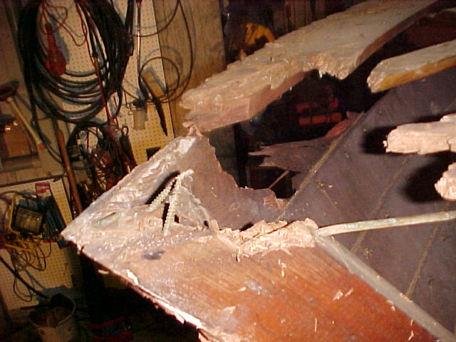
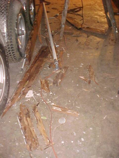
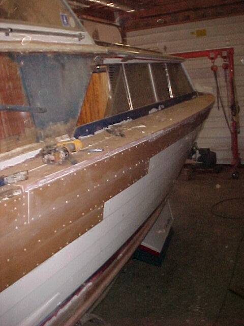
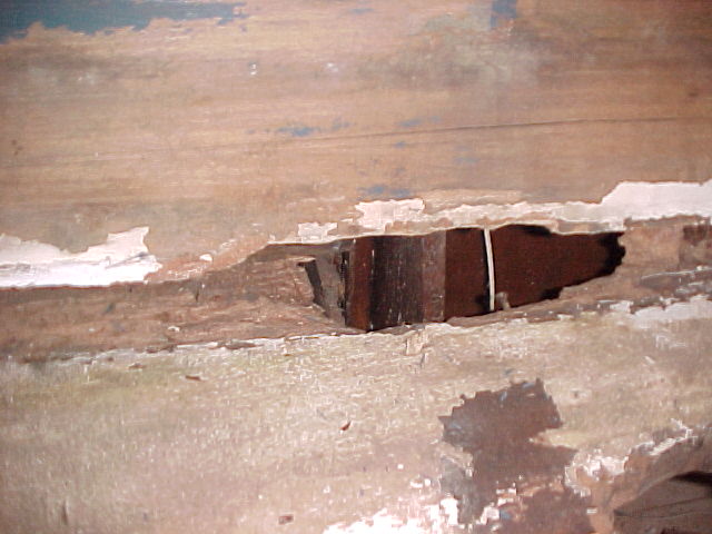
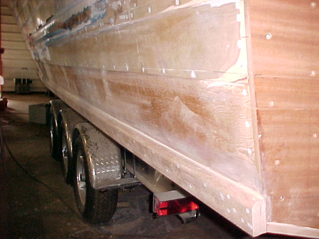
The three photos above illustrate the rot repair required to the ends of the lapstrake planks on the hull sides. This will be completed with new 1/2 " marine plywood treated with Smiths CPES.
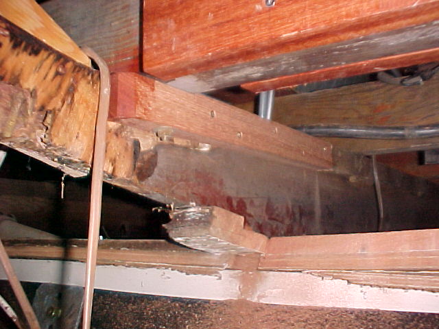
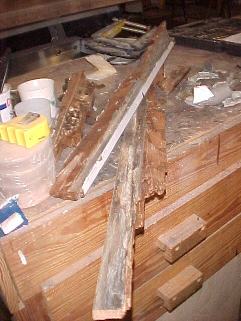
The 2 photos above illustrate the poor condition of 3 of the 4 stringers. The forth stringer, oddly, was not effected by rot.
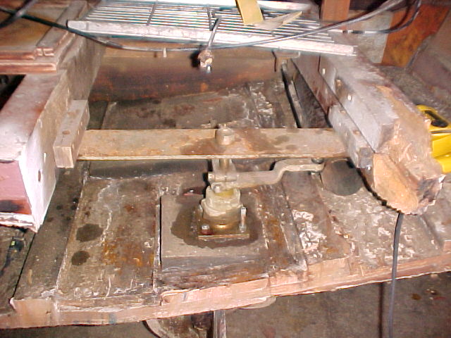
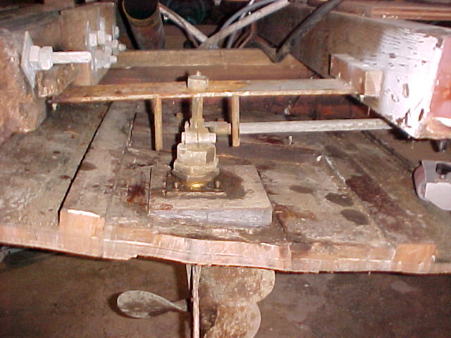
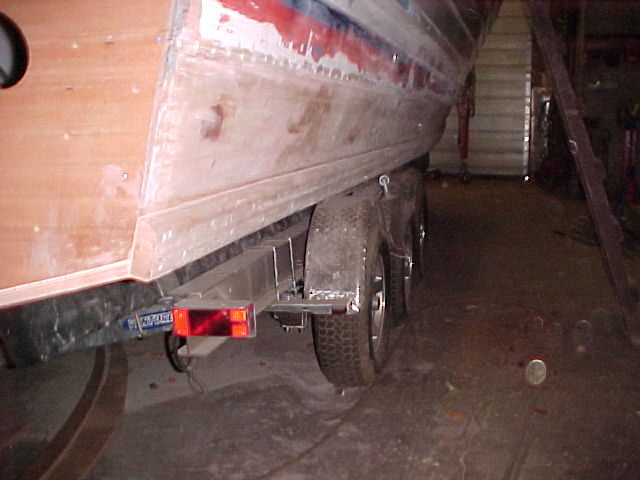
These photos are to reference when re-installing the rudder assembly.
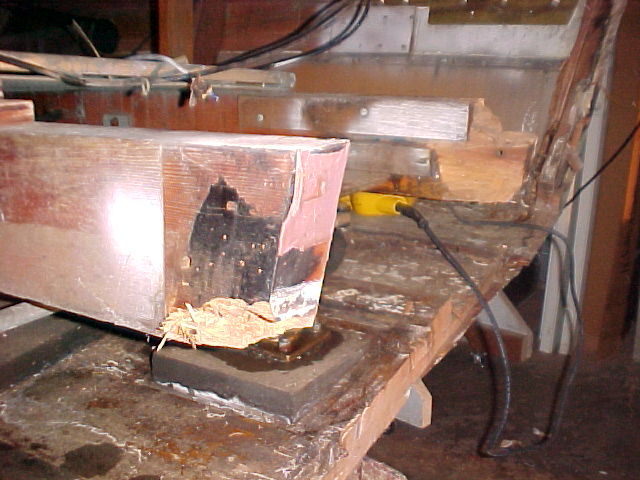
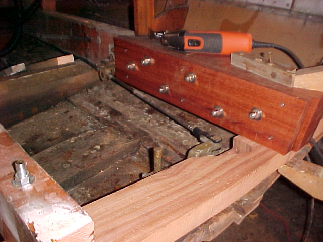
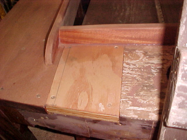
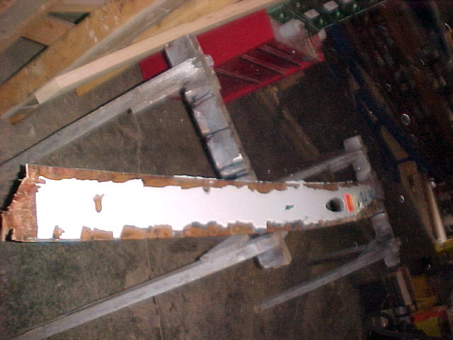
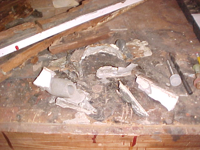
Shown are the transom bow and transom shelf laid out across the table saw. Each of these will be duplicated with new wood. The picture to the right shows the materials removed from the transom to access the problems we found in the transom during the survey last November.
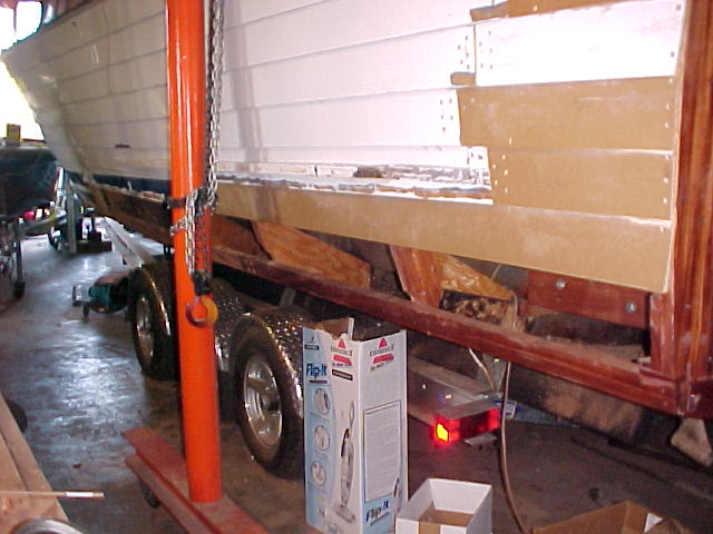
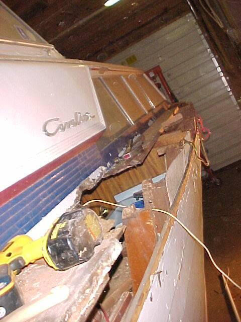
This is what the 33 Sea Strake Cruiser looks like with the transom removed! This exposed not only the rot we suspected, but additional rot from the transom shelf (just above the level of the water tank seen in the photo).
And, at the end of the day! SEE BELOW!
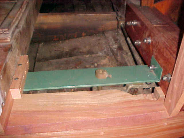
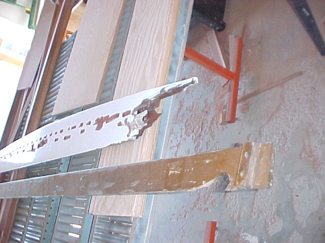
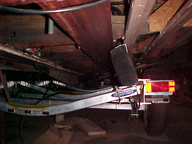
The transom frame is nearly complete and the steering supports have been modified to fit the smaller space created when the stringers were sister framed. These rusty old units were shortened, angle iron welded to one end (right end in this photo) and treated with Extend rust treatment and painted before re-installation.
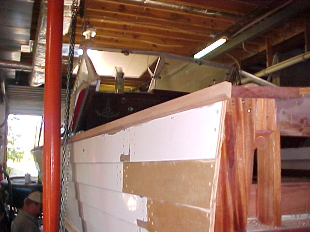
The shower rinse system has been re-located to the port side making room for some convenience pockets in the center of the cockpit at the transom.
Update September 12, 2008
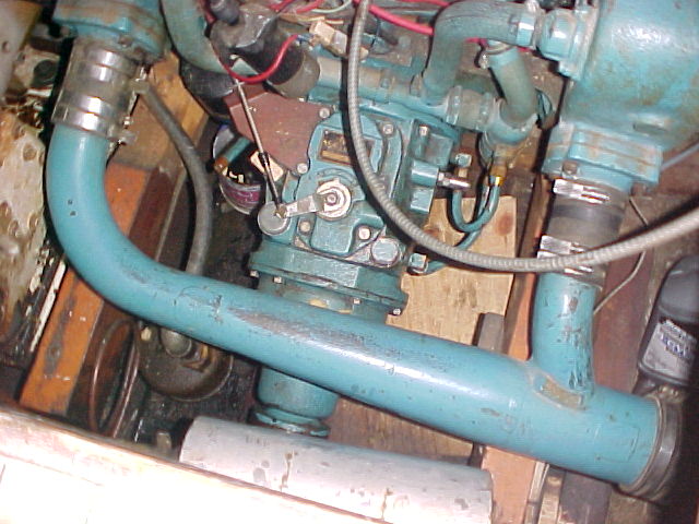
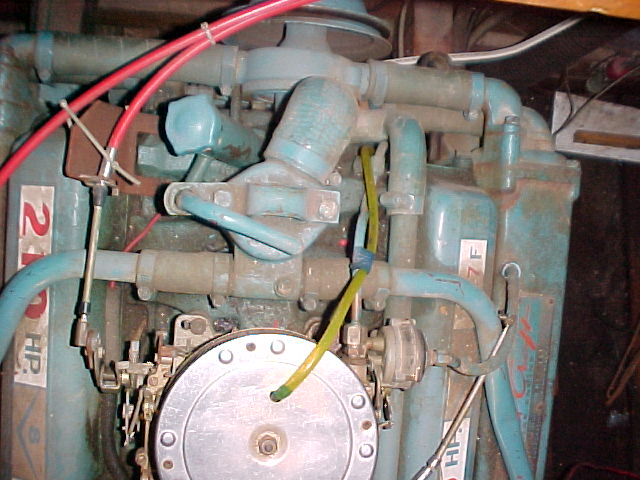
Belts and hoses were cataloged with about 10 pictures similar to these so that replacements could be made in groups. There are many more belts and hoses on a Marine engine than a standard automotive engine of similar size and horsepower, and you can't just call up the parts store and order "a set of hoses and belts for a 327F". To minimize the time required to replace these hoses, the cataloging was completed, then all belts and hoses were removed from ONE engine. About 1/2 of the hoses were specially preformed for the application back in 1968. These hoses per say are no longer available, so what has to be done is the hose matched to a similar hose that may have be used for other more current applications such as late model cars. Some hoses had to be cut from longer hoses that had even more twists turns and bends, but had a small section in the middle that matched our needs.
All of these hoses are now cataloged - so if the owner or others someday need a new set of hoses for a 327F we can provide the ones needed.
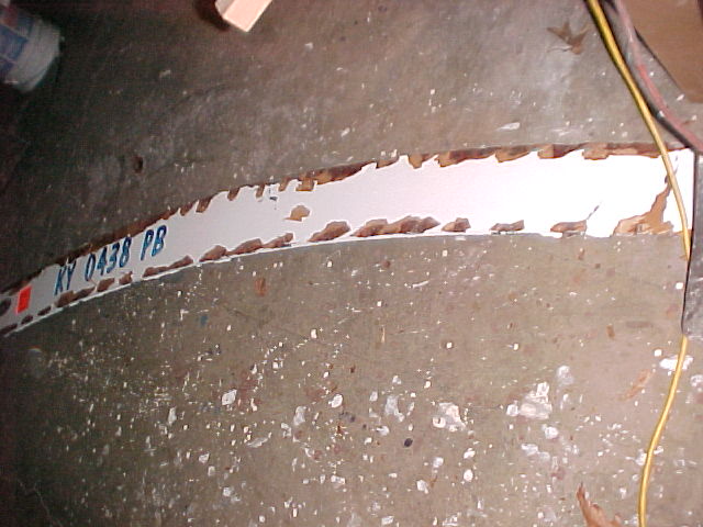
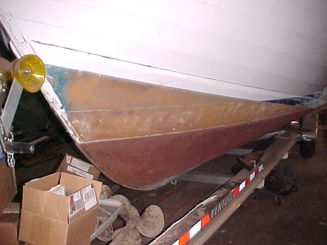
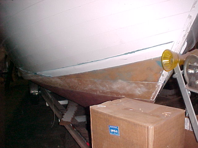
The removal of the rot damaged lower strake on both the Port and Starboard sides of the boat resulted in the discovery of extensive rot in the chine on both sides. Approximately 15 feet of chine was removed and replaced on the Port side, and 8 feet on the Starboard side. Sides shown on their respective sides here.
Also discovered was rot in the side Stakes ( the vertical supports attached to the ribs) at rib stations 2 and 3 from the stern on both the starboard and port sides. The rotted portion was removed and new wood sistered in. The plywood gussets were also replaced and everything treated with Smiths CPES
We have completed all the work to the cockpit! See below
Bottom Work!
Port and Starboard Gas filler enclosures
Port rub rail
Port deck replacement
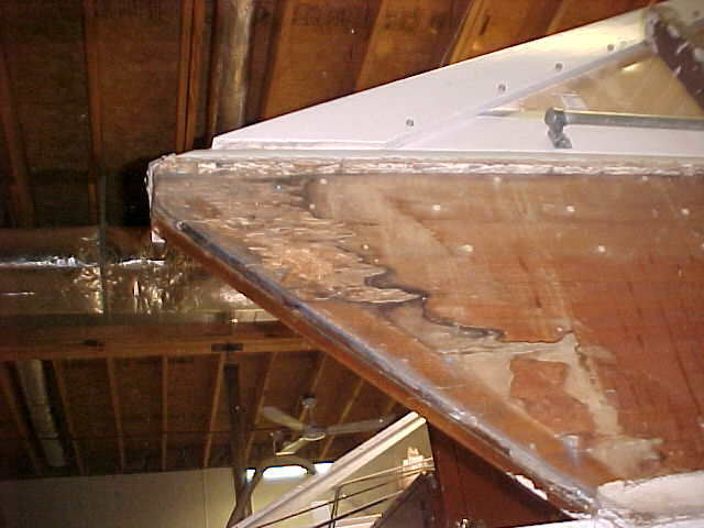
Transom - cut out rot and replace section of aft deck over transom
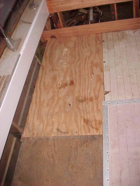
New floor panel in starboard / aft Corner of cockpit. T
Starboard Station 2 from stern - sister only.
Starboard Station 1 from stern - sister and new gusset.
Port Station 1 and 2 from stern - sister and new gusset.
At station 1 from stern rot was discovered in a member attached to the rib that bolts the rib to the longitudinal engine stringer so naturally it had to be replaced!
Bottom removal has begun - the bottom is removed from the chine to the shaft logs 9 feet up from stern. The longitudinal supports for the bottom (which are made of two layers of mahogany ) were rotted up to the engine compartment area between station 3 and 4 from stern.
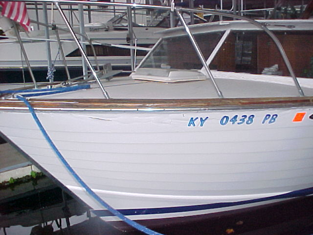
1965 Chris Craft Cavalier Division 33' Sea Strake
Update December 12, 2008
Bottom removal is 99% complete to the splice 20 feet forward of the stern - to where we are replacing the bottom. . There are only a few small areas remaining that have to have the bottom removed. They are the areas where blocking was used to support the boat while the bottom was being removed.
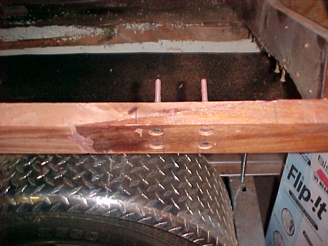
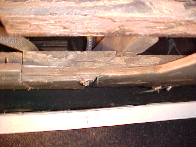
Pictured above is a longitudinal stringer that was both broken and rotted at a frame station! This of course gets replaced with the new bottom. We found it more cost effective to remove these stringers with the bottom, than to separate the bottom from them.
The starboard side has the bottom 99% removed and two of the 4 longitudinal supports have been installed and connected to the original ones in the forward 1/3 of the hull. Photo above is from stern. To right is looking toward stern near splice. Below is Starboard splice.
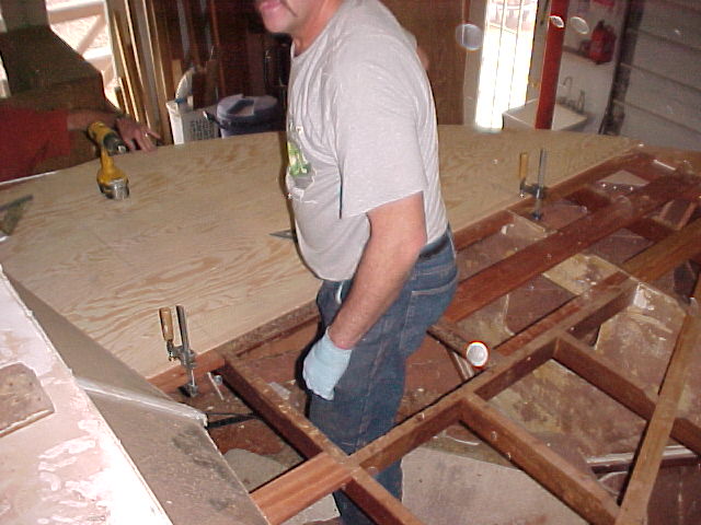
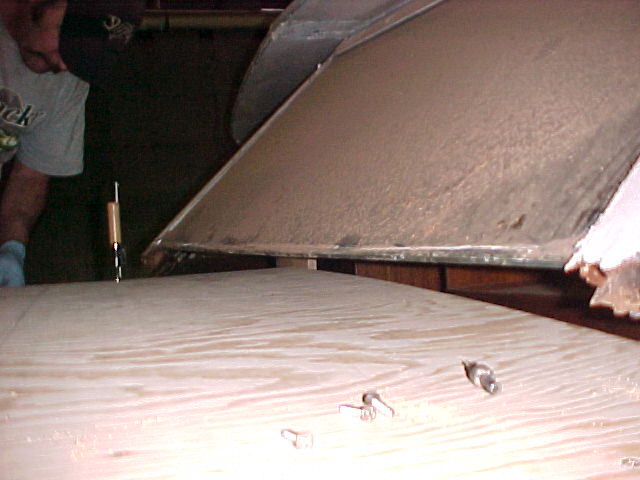
The port side has the bottom 100% removed (to splice) and all 4 of the 4 longitudinal supports have been installed and connected to the original ones in the forward 1/3 of the hull. Photo above is from stern. To right is looking from the splice toward the stern. Below is the new 3/4" hydrocore BS1088 certified Lloyds approved plywood. CPESed and ready to go on the bottom!
We expect to be able to start installing the plywood on Wednesday.
There were some water lines cut in the bottom removal process, and there is a main engine stringer that has some rot on the side that still needs attention before we begin installing the play. We will start from the forward splice and install our panels toward the stern so that the only adjustment of panel shapes and sizes will be at the stern! This will save time and installation effort.
Update January 21, 2009
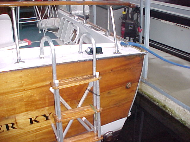
The ladder is wider thicker and has just ever so slightly smaller hand holds to make it as sturdy as possible. The ladder it was modeled after DID last 40 or more years, but appeared to have been repaired and or modified a number of times!
The Transom is made of 1 piece of Transom plywood 10feet by 5 feet nominal. It is BS1088 certified Marine Sapele quarter sawn ribbon stripe plywood. And yes... it is just as expensive as it sounds!
The transom plywood (and also the bottom plywood) measures 10 feet 2-1/4 long! Go figure!
Installing, trimming, and fairing the transom was the last step before replacing the bottom... as the bottom plywood extends below the edge of the transom thus covering the transom to transom bow joint. This way water will rush by this joint and protected the transom plywood edge.
Other jobs completed in the last two weeks include but are not limited to:
- Check sand, smooth keel rabbet and splices
- Plug screw holes in keel, chine and splices
- Remove long screws used to speed installation of longitudinal stringers and replace with shorter ones so that sharp screw points do not protrude out of longitudinal stringers and damage plumbing or electrical. Some of these screws had to be cut off with an abrasive wheel.
- Tighten all keel and engine stringer to rib connection bolts and inspect keel and stringers for rot. Also removed all abandoned battery boxes, wire loom holders etc.
- Repair rotted rib to stringer joint found during inspection process above!
- Install flow through exhaust on port side, prepare for installation on Starboard side
- CPES all structural members
- Turn crapper tank (sanitary holding tank) end for end and change mount for same
- Re- plumb transmission on port side as we are not removing / rebuilding it laterally
- Get screw size and count for bottom replacement.
Update February 25, 2009
THE BOTTOM IS ON!!!!
The bottom is on... Last Tuesday we got the Yard Arms picked up, delivered, in place, and also used railroad jacks under the keel to support it. On Wednesday we installed some extra wood on the top of the keel so that longer screws could be used that have more holding power than was originally used. Also that day one sheet of plywood (starboard fwd) was installed. On Thursday the 19th we managed to install two sheets (port fwd and port aft) and on Friday we installed Starboard aft and also put all the fasteners in the splices as some of the fasteners were through bolts. We have a new word that we invented.... Squozage! We used 25 tubes of 3M 5200 caulk on the bottom. 5 of those were left from the original purchase, making the total usage of 45 tubes. We coated every surface liberally so that the sealant was forced in to any and all spaces between structure and plywood. Probably the equivalent of 2 tubes squeezed out and made it to the floor (and our clothes ) before we could get it cleaned up! This will ensure a waterproof seal not only at the keel, chines, and transom, but also between the structural members and the bottom so water and debris can not collect between those surfaces and cause rot. This is also in keeping with the way Chris Craft did it back in 1966 on this their 4th attempt at building this hull!
This is a view inside of the bottom showing the "Squozage" from the chine (right) and a longitudinal runner (left)
There is still plenty of bottom work remaining.... All the screw holes have to be filled with a two part filler, and sanded, painted with epoxy barrier cote and then bottom paint. The bottom also has to be faired to the sides of the hull, and the spray rail fabricated and installed. Through hulls have to be installed for the engines, head, and generator. The Bottom has to be drilled for the prop shaft and the shaft and log assemblies have to be installed. The bottom also has to be drilled for the rudders and those packing glands and rudder assemblies installed. ALSO.... we also have to investigate / plug some transverse holes in the keel. These processes started yesterday with one person and will continue at least the rest of the week.
Update March 12, 2009
Once the bottom was in place it sat undisturbed for 7 days while the 3M 5200 completely cured. Essentially the boat is glued together with this adhesive sealant and the screws only held the assembly together until the 3M 5200 adhesive sealer set. Screw holes in the bottom were filled and the bottom painted with 2 coats of Interlux Epoxy Barrier Kote and then 2 coats of Fiberglass Bottom Kote in the original Copper bronze color.
The fwd 1/3 of the bottom of the boat was in excellent shape except for one area that had been damaged by one of the previous owners. There was evidence of physical damage caused by any number of possible reasons such as running aground, or hitting an object. The plywood had been damaged and water had infiltrated the fracture for long enough for rot to form in a small isolated section. We were actually able to take a small 6 oz ball peen hammer to the section and very easily penetrate the plywood. Note the ice pick marks... they follow the original crack that was due to some physical damage. This area was cut back to plywood of good integrity and a replacement was applied to the effected area. Fairing of the replacement was accomplished with this vacuum assisted tool costing several hundred dollars. We use the latest technology in tools and have the right tool to minimize hourly costs for virtually every conceivable job.
There was a small amount of rot in the stem and it was removed and the end of the stem replaced. The Breast hook as also rotted and replaced. The "covering boards" - actually structural members the deck will attach to as shown in the photo as well. These are in the process of being fabricated and installed as this update is being written.
Update March 22, 2009
Upon removal of the vinyl decking by the owner, lots of rot was discovered on the Starboard side of the cabin deck. When the top strake of planks was removed even MORE rot was found.
To the left you can see how much decking had to be removed. Center, see the condition it was in as it was removed. To the right - the finished product.
There were two layers of wood. The deck level which was 1-1/8" thick and the sheer batten level which was 5/8" thick. The sheer battens fasten to the underside of the deck and are beveled at the same angle as the top strake of planks. This angle changes from almost verticle at the back of the boat to almost a 45 degree angle at the bow. The sheer batten is also curved, making it very difficult and time con$uming to fabricate and install.
You've probably heard the old saying... "When your up to your ass in alligators it is difficult to remember your objective was just to drain the swamp". Our draining of the swamp was to remove and replace the top strake of planks which had rotted all along the top edge. The Alligators were - What we found - no solid structure to attach the new strake to!
See the transformation!
Update March 28, 2009
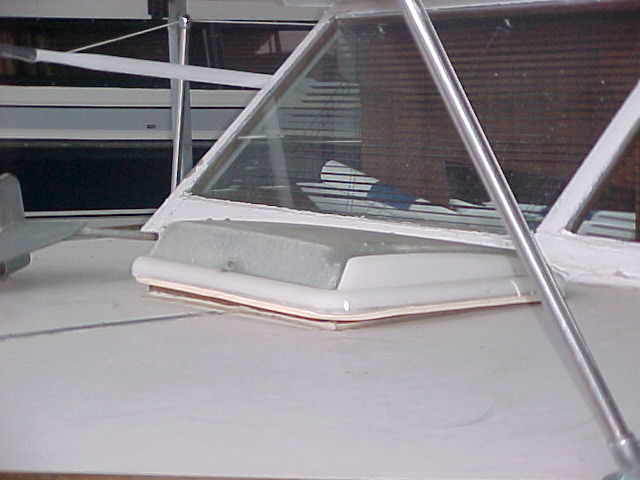
There is a new additional deck beam on the boat as the windshield was actually being -poorly supported by the original deck. This beam is intentionally thicker than the original beams for additional strenth.
This week we fabricated and installed new structural members in the deck, and then installed the deck. All the structural members installed new or replaced.
Essentially all new structure was required with the exception of the deck beams. They were essentially void of rot. There were a couple that had a little on the ends, but we were able to cut it out and then treat the beam with CPES and still make great attachements to the new structure.
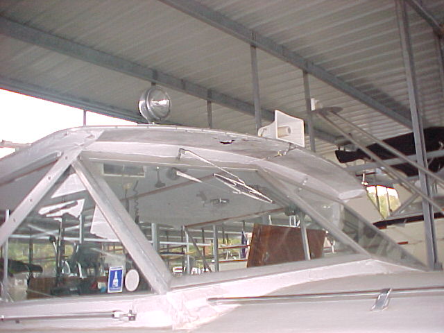
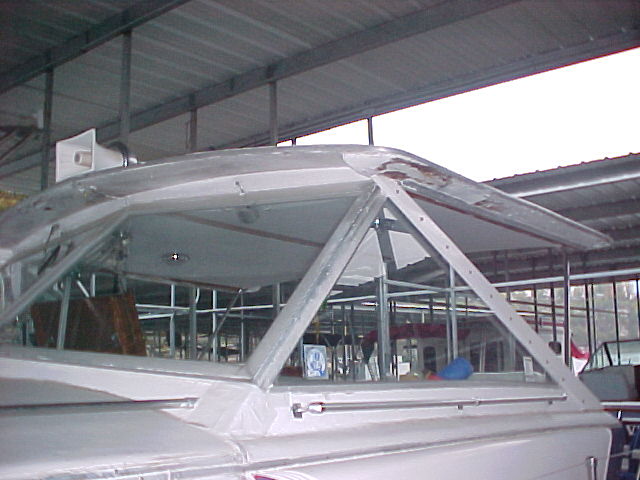
Once the structure was in place which requred 2 days, the deck was placed, fastened down, trimmed and CPESed in one day with two workers. Note the rotted ends of the windshield in the photo above, and the transformation below.
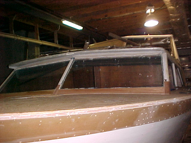
The new windshield frame ends and bottoms were fabricated and installed. The old windshield frames were cutt off above the rotted area and new pieces fabricated to fit. The Port windshield bottom was un usable and the stb side was questionable so new bottoms were made.
The next challenge was at the bottom of the port side windows. It appeared we had a couple of feet of wood rotted away, but as we tore it out we discovered the entire 12 foot length of the window frame was rotted and had been bondoed over. The rot extended under the fiberglass cowell and into the bulkhead in the galley area.
It is realy curious - there was just a small amount of deck that was rotted on this the port side, but an enourmous amount of rot on the starboard side. However the window frame on the port side was completely gone and only a little rot was found on the Starboard side?!?!?
Above, and to the right
The rotted Port side sliding window frame. Note foam had been put in one void and bondoed over
Sorry for the poor focus, but the picture on the right shows the floor support that had a rotted section removed and was sister framed after discovery of rot in the original support.
To the left is the repaired bulkhead in the head.
The painting effort was begun with the removal of cracked paint under the spray rail where it gets a bit more flexing than the rest of the boat. Also note the re- etched in boot stripe and bottom paint / water lines.
The week started out with a bang.. wiht both spray rails being attached early on. There is a layer of 5200 between the spray rail and the bottom to hull side joint - virtually eliminatint the possiblity of leakage from the chine.
Page 1
New Toll Free Phone Number 866-921-2628
 | ||||||